

BA RoofOn V30 R16 12_2012 GB mit CE BAK.doc
5
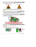
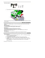
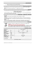
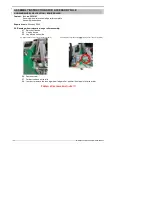
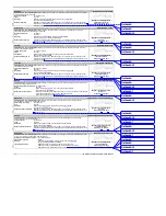
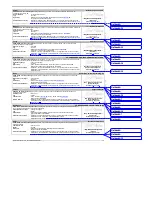
Guide roller adjustment:
Space
for
welding
line with
10mm
20mm
20mm
30mm
30mm
40mm
•
Bring the welding machine into the right welding position.
Outside edge of the overlap, outside edge of the pressure roller and outside edge of the guide roller must form
a line (see image).
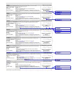
WELDING PARAMETERS
Caution:
Before any welding operation, a test weld should be performed so as to determine the welding
parameters.
Welding temperature:
The welding temperature is adjusted with a potentiometer or control unit.
Do not start welding before the set temperature has been reached.
Welding speed:
The welding speed is adjusted using a potentiometer or control unit.
The drive starts automatically when the welding machine is swivelled in.
The welding speed is adjusted with the potentiometer or control unit depending on the plastic film,
geomembrane liner or weather conditions.
Welding pressure:
The welding pressure is directly applied onto the pressure roller by the weight of the machine.
WELDING
Operating conditions:
•
Maintain the maximum allowed network impedance (Z
max
= 0.301 Ω + j 0.188 Ω) and consult your
local electricity supply board if necessary.
•
Check the configuration of the nozzle.
•
The mains connection must conform to ICE 60364 as well as to national standards.
•
Connect the device to the grid. The voltage rating must correspond to the specifications on the
nameplate.
•
When using extension cords, a minimum diameter of the cable must be observed. Cable length up
to 25 m, diameter 2.5 mm² (for automatic welding machines with 120 V, we recommend a
diameter of 4.0 mm²).


