Copyright 2020 Baker Hughes Company. All rights reserved.
Page 138 of 277
5.5
Setup Digital Inputs
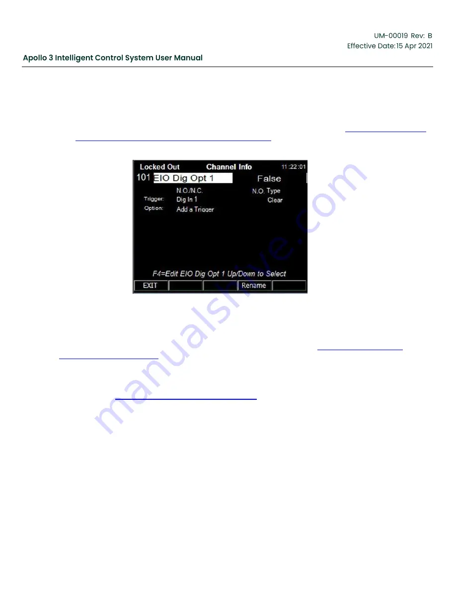
Digital Inputs are configured using the Channel Info screens for the inputs. The navigation path is Home
Screen -> Data -> Digital I/O -> the desired I/O to configure.
The Channel Info screen for the first digital I/O on the Apollo I/O board is shown in
Screen for 1st Digital I/O on the Apollo I/O Board, page 138
Figure 115: Channel Info Screen for 1st Digital I/O on the Apollo I/O Board
Digital Inputs on the drive module (V7Dig In x) are input only. Digital I/O on the Apollo I/O board can be
configured as either inputs or outputs. Note that the correct relay/input module must be installed in the I/O
board. Digital Outputs are configured when they are attached to a trigger. See
for discussion on setting up digital outputs.
Digital inputs are Normally Open by default and are connected to a Stop->Fault trigger. This allows Apollo to
run without adding any jumpers across unused digital inputs. Most field sensors are normally closed and
then open to report a fault. Configure the N.O./N.C. as needed and rename the channel (and connected
trigger) as in the
Section 5.4 Setup Analog Inputs, page 132
Summary of Contents for Apollo 3
Page 1: ...Copyright 2020 Baker Hughes Company All rights reserved Page 1 of 277...
Page 266: ...Copyright 2020 Baker Hughes Company All rights reserved Page 266 of 277 Figure 227 USB Menu...
Page 267: ......
Page 276: ......
Page 277: ...Index 129112 28 197705 28 197349 28 800638 28 197350 28 810280 28 197351 29...


