28 |
Baker Hughes
© 2020 Baker Hughes Company. All rights reserved.
as indicated. See Figure 61
and Table 18 in the
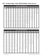
Maintenance Tools and Supplies section for drift
pin size.
• Use a light machinist hammer to tap each pin
alternately until the disc snaps out of the recess in
the disc holder.
15. For O-Ring seat seal valves only, remove the Retainer
Lock Screw(s), O-Ring Retainer, and O-Ring Seat
Seal.
ATTENTION!
!
The nozzle is normally removed for routine maintenance
and service.
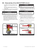
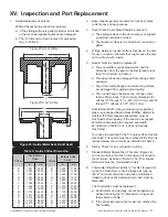
16. The nozzle is threaded onto the base and is removed
by turning it counterclockwise (from right to left).
Before removing the nozzle, soak the threaded joint
with a suitable penetrating liquid or solvent. If the
nozzle is frozen to the base, apply dry ice or other
cooling medium to the inside of the nozzle and heat
the base from the outside with a blowtorch in the area
of the nozzle threads.
ATTENTION!
!
Should heat be applied, use care to prevent cracking of
cast parts.
17. Using a three- or four-jaw chuck welded vertically to a
stand bolted to a concrete floor, clamp the nozzle into
the chuck and break the body loose with a heavy rod
or pipe (Figure 17).
ATTENTION!
!
Exercise care when inserting a rod or pipe in the outlet.
Ensure the valve nozzle is not damaged during the
operation.
18. Use a large pipe wrench on the nozzle flange to
remove the nozzle from the base (Figure 16).
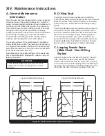
19. Remove the Nozzle from the Valve Base as
suggested in Figure 16, or by using a Hex wrench or
a pipe wrench on the flange as indicated in Figure
17.
20. The Main valve is ready for cleaning, inspection and
refurbishing.
21. Discard all O-Rings, guide rings, and seals.
XIII. Disassembly of the 2900-40 POSRV (Cont.)
Base
Nozzle
3 Jaw Chuck
Chuck Stand
8' (2.4 m)-10' (3 m)
Long Rod or
Heavy Pipe
Figure 16: Loosening the Nozzle from the Base
Base
Nozzle
Pipe Wrench
View From Top
View From Side
Figure 17: Removing the Nozzle from the Base


