30 |
Baker Hughes
© 2020 Baker Hughes Company. All rights reserved.
XIV. Maintenance Instructions
A. General Maintenance
Information
After the valve has been disassembled, a close inspection
should be made of the seating surfaces. In a majority of
cases, a simple lapping of seats is all that is necessary to
put the valve in first class working order. If an inspection
of the parts shows the valve seating surfaces to be badly
damaged, machining will be required before lapping.
O-Ring seat seal valve nozzles can only be reconditioned
by machining, not lapping. (For specific information
concerning the machining of nozzle and disc seating
surfaces, see Paragraphs F and G which follow.)
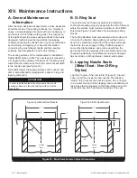
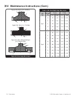
The seating surfaces of the metal seated Consolidated
Safety Relief Valve are flat. The nozzle seat is relieved by
a 5° angle on the outside of the flat seat. The disc seat is
wider than the nozzle seat; thus, the control of seat width
is the nozzle seat (see Figure 18).
Reconditioning of the seating surfaces of the nozzle and
disc is accomplished by lapping with a cast iron lap, and
lapping compound.
ATTENTION!
!
In order to establish leak free valve seats, the nozzle
seating surface and the disc seating surface must be
lapped flat.
B. O-Ring Seat
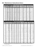
The nozzle must not have any defects to prohibit the
O-Ring from sealing properly, especially the OD of the seat
where the surface must maintain a minimum of 32 RMS
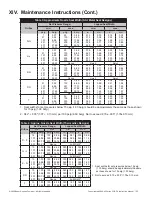
finish. See Figure 18 and Table 2 for reworking O-Ring
Nozzle.
The O-Ring Retainer must also maintain a flat surface for
it to sit on the Nozzle. Only polishing of surface can be
done since material removal from this surface will cause
the Nozzle to over engage O-Ring. Polishing paper or
some other light abrasive can only be used since the
part cannot function properly if its overall dimensions are
changed significantly. If significant corrosion or damage
has occurred on O-Ring retainer, discard and replace.
C. Lapping Nozzle Seats
(Metal Seat - Non-O-Ring
Styles)
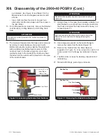
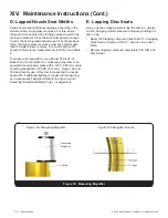
Lap the 5º angle of the nozzle first (Figure 19, View A).
Then, invert the nozzle lap and use the flat side as a
“starter” lap to ensure the seat is square. Use a ring lap
in a circular motion to finish lapping and reconditioning of
laps. Keep the lap squarely on the flat surface and avoid
rocking the lap, which will cause rounding of the seat.
C
B
D
F
45°
Nozzle
Bore
C
B
D
F
45°
5°
Nozzle
Bore
Figure 18a: Metal Seat Nozzle
Figure 18b: Soft Seat Nozzle
Figure 18: Main Valve Nozzle Critical Dimensions


