Consolidated 2900-40 Series POSRV Instruction Manual
| 69
© 2020 Baker Hughes Company. All rights reserved.
XXIII. Maintenance Tools and Supplies (Cont.)
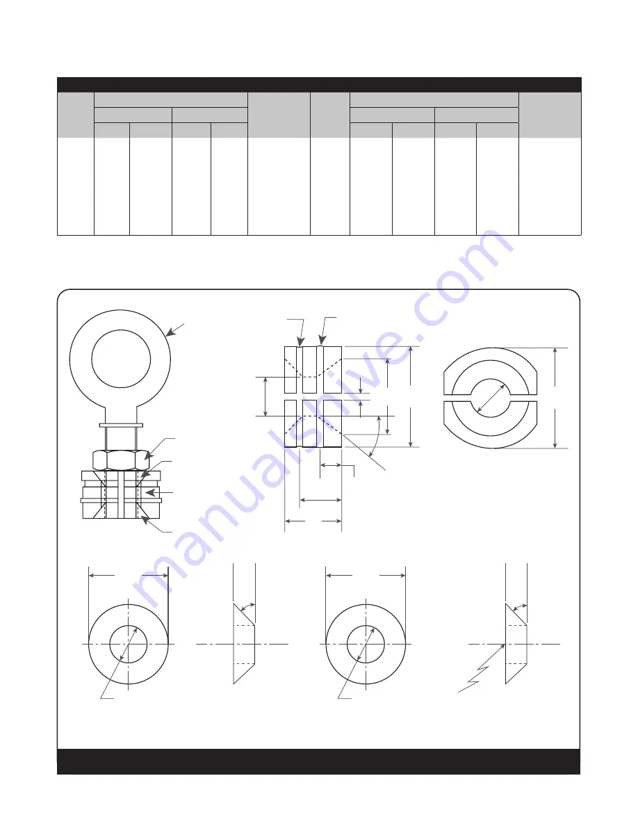
D. Disc Holder and Guide Removal and Assembly Tool
DET. 2
DET. 3
DET. 3
DET. 4
DET. 4
DET. 5
A
M THREADS
DET. 5
Ø L HOLE
DRILL
45
0
K
K
C
C
E
D
H
I
J
G
F
DET.1
45°
D
Ø M HOLE
DRILL
45
0
Figure 62: Disc Holder and Guide Removal and Assembly Tool
Table 17: Wrench Types
Valve
Orifice
Description of Wrench
Pin Spanner
Wrench No.
Valve
Orifice
Description of Wrench
Pin Spanner
Wrench No.
Wrench Radius
Pin
Wrench Radius
Pin
in
mm
in
mm
in
mm
in
mm
F
.750
19.05
.219
5.56
4451801
M
1.675
42.55
.328
8.33
4451806
G
.750
19.05
.219
5.56
4451801
N
1.875
47.63
.359
9.13
4451607
H
.875
22.23
.266
6.75
4451802
P
1.875
47.63
.359
9.13
4451607
J
1.125
28.58
.266
6.75
4451803
Q
2.500
63.50
.438
11.11
4451808
K
1.250
31.75
.281
7.14
4451804
R
3.000
76.20
.500
12.70
4451809
L
1.375
34.93
.297
7.54
4451805
T
3.750
95.25
.500
12.70
4451810


