Masoneilan SVI3 Installation and Maintenance Manual
=
| 27
© 2021 Baker Hughes Company. All rights reserved.
2. Bolt the extension shaft to the valve position take-off shaft using a 1/4 - 28 UNF
socket flathead screw. Secure the machine screw holding the extension shaft with a
torque of 144 in-lbs (16.269 N-m) using 5/32" Hex Key.
3. Ensure the endplay from the vacuum position to the fully extended position is less
than 0.06 in. (1.524 mm).
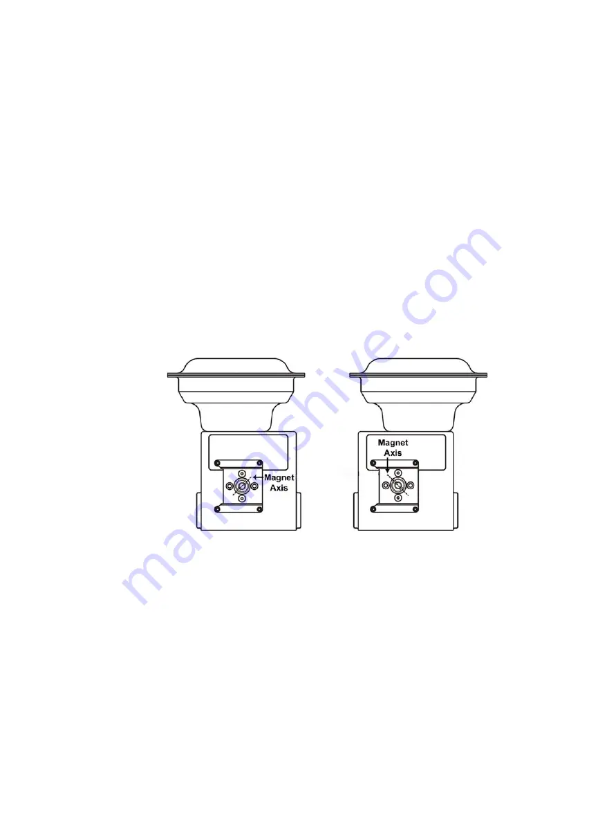
4. Slide the magnet holder into the extension shaft. The location of the magnets is in the
ring of the magnet holder. The magnetic axis is the imaginary line through the center
of both magnets (See Figure 9).
Figure 9 Magnet Axis
NOTE : Upon internal valve pressure the thrust shaft is pushed out to the mechanical
stops, usually a thrust bearing. On valves where the valve position take-off is
mounted directly on the end of the plug shaft, a Camflex for example, the
shaft must be bearing on its stop to properly set up the SVI3 digital valve
positioner. During hydrostatic testing the shaft is thrust to its stop and a
normally tightened packing retains it in that position.
NOTE : On vacuum service, the valve shaft can be drawn into the body by the vacuum
acting on the shaft, but the magnetic coupling must be assembled flush with
the mounting bracket with the shaft pulled fully out to its thrust bearing.


