38 | Baker Hughes.
© 2021 Baker Hughes Company. All rights reserved.
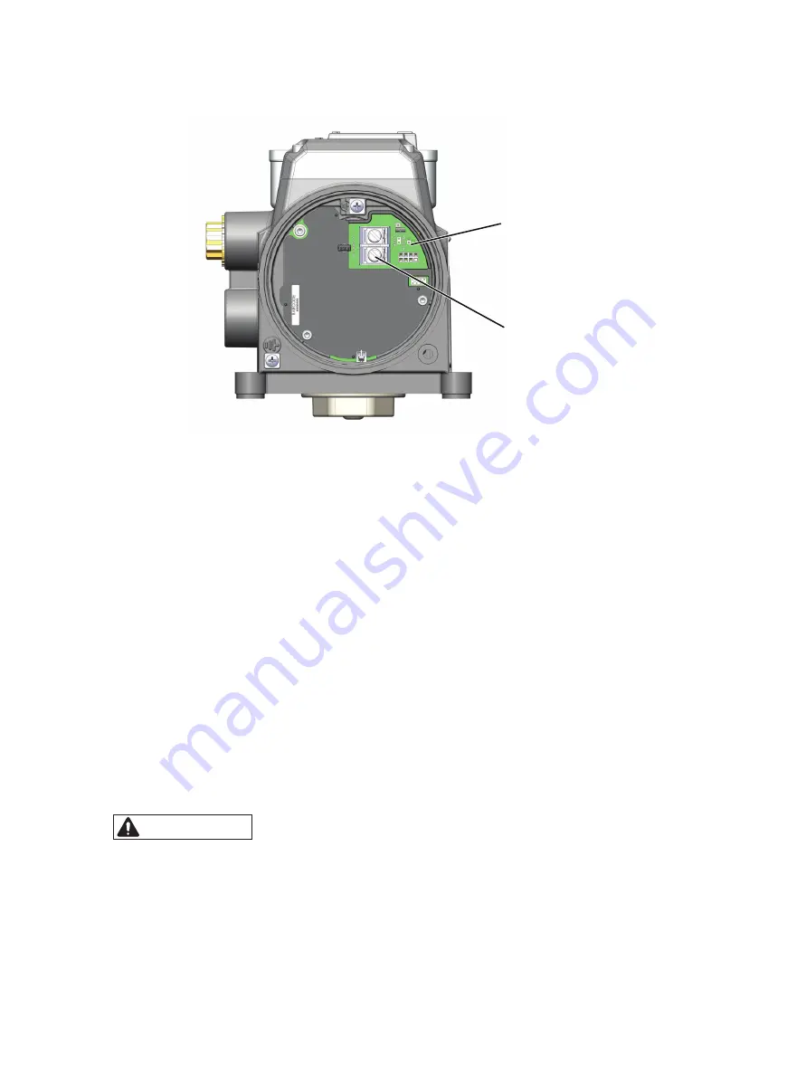
Figure 17 Connections to Main Electronics Module (via Terminal Board)
6. Unscrew the required connector, insert the control loop wire with correct polarity and
tighten the connector screw.
7. Reinstall the cover.
3.6.4 Wiring an Options Board
The options board contains connections for the following:
• Two solid-state switches (SW#1 and SW#2) configurable to various alert/status
bits and open/close states.
• 4-20 mA OUT to support position retransmit functions.
• Digital Input (DI) connection.
• REMOTE connection to wire a Masoneilan remote position sensor.
• Process Variable (PV) input, a 1-5V input which can accept a position sensor input.
The Options board can be ordered together with positioner or can be purchased
separately.
CAUTION
For proper operation, maintain signal po and - respectively.
Options Board Terminal connections must be wired using a wire of
26 AWG to 14 AWG size and terminal torque between 0.5 - 0.6 Nm.
Configuration Lock
Jumper
(rotate to engage)
4- 20 mA
Input Signal


