42 | Baker Hughes.
© 2021 Baker Hughes Company. All rights reserved.
Switch Settings
The two digital output switches can be opened or closed in response to conditions that the SVI3
detects. Please Refer SVI3 DTM Manual to learn more about the configurable conditions and procedure to
configure them.
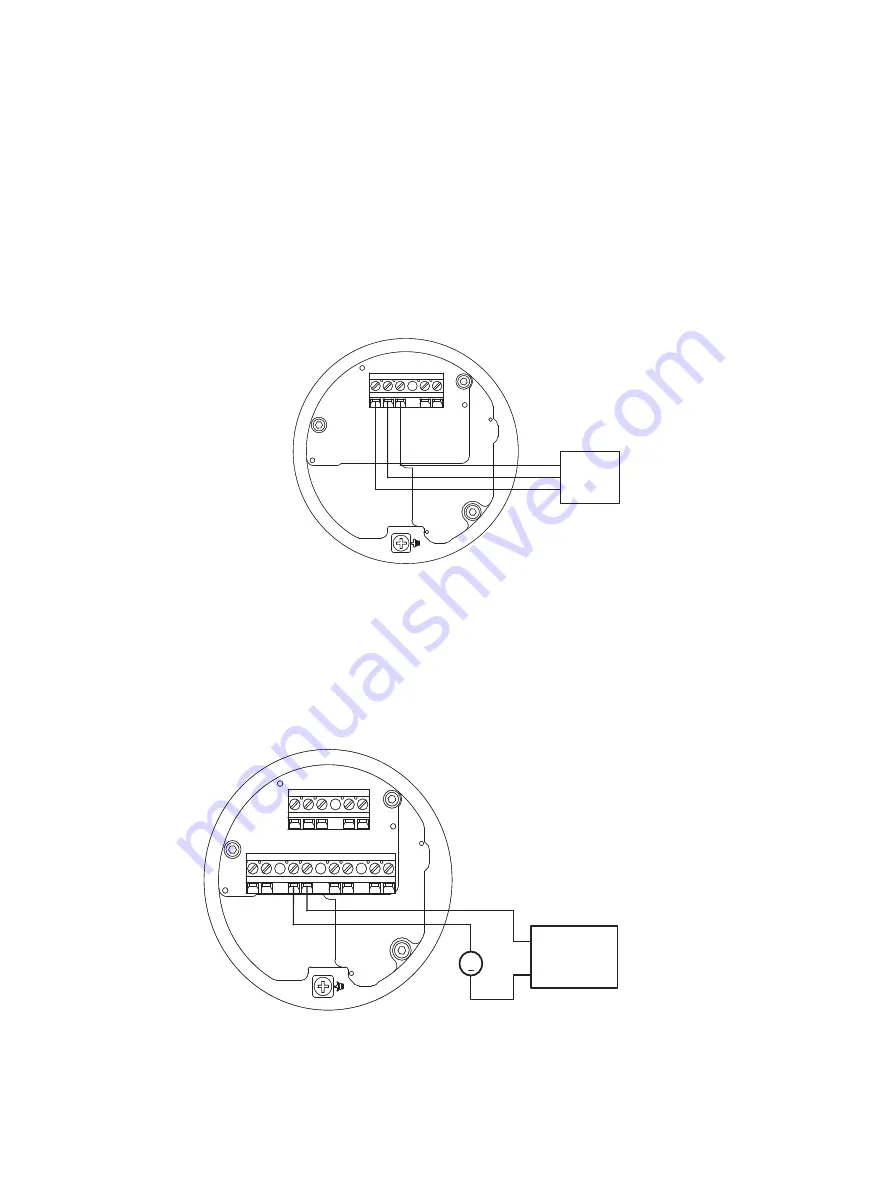
Remote Position Sensor Input Connections
Follow the procedure for “Connecting to the Control Loop” on page 37 and connect to
REMOTE. See Masoneilan Remote Position Sensor (RPS) Quick Start Guide Quick Start
Guide, which is downloadable at https://valves.bakerhughes.com/resource-center.
Figure 22 Remote Position Sensor Input Connections
Retransmit Connections
Follow the procedure for “Wiring an Options Board” on page 38 and connect to 4-20mA
OUT. Connections to the non-Masoneilan devices depend on their documentation.
Figure 23 Retransmit Connections
SVI3
REMOTE
PV
1-5Vdc
1
2
3
+
-
REMOTE
PV
1-5Vdc
1
2
3
+
-
Remote
Posion
Sensor
SVI3
+
+
Voltage
Source 24V
REMOTE
PV
1-5Vdc
D/I
+ -
4-20mA OUT
+ -
1
SW #2
+ -
SW #1
+ -
2
3
+ -
REMOTE
PV
1-5Vdc
D/I
+ -
4-20mA OUT
+ -
1
SW #2
+ -
SW #1
+ -
2
3
+ -
Control System
4-20mA Input
Typical Output Current: 4-20mA
Typical Operating Voltage: 10-30V
Maximum Current Limit: 30mA


