© 2021 Baker Hughes Company. All rights reserved.
Masoneilan SVI3 Quick Start Guide | 13
1.
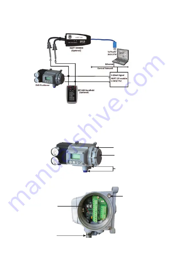
Disengage the lock screw before removing the end cover.
2.
Unscrew the end cover and remove the 1/2” NPT plastic cover for cabling. The user can
remove additional 1/2” NPT plug if extra ports are needed.
3. To connect the SVI3 to the control loop, use the suitable cable gland as per the end user
country regulations.
Lock Screw
End Cover
1/2” NPT Housing Entries
Figure 15 - SVI3
Digital Positioner
(front view)
SVI3 Wiring Procedure
The SVI3 uses a 4-20mA signal with HART communications to control the connected pneumatic
actuator. This section describes the SVI3 wiring configuration via ValVue3/SVI3 DTM software
and HART I/O modules (for PLC and DCS), or a HART modem/HART handheld communicator.
Figure 14 - Wiring Diagram
4-20 mA Signal
Cable Gland
Lock Screw
Figure 16 - Connections to Main Electronics Module


