background image

Table of Content

Introduction ......................................................................................3
Product Quality ................................................................................3
Safety .................................................................................................3

Pre-operational Safety Checklist ..................................................... 3
Operational Safety Checklist ........................................................... 4

Features ............................................................................................5
Included ............................................................................................5

Specifications

 ....................................................................................6

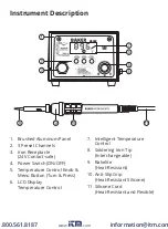
Instrument Description ...................................................................7
Operating Instructions ....................................................................8

Setting Pre-Set Memory Channels ................................................... 9
Selecting Temperature Unit of Measure ......................................... 9
Enabling/Disabling the Soldering Iron Sleep Function ............... 10
Enabling/Disabling the Auto Power OFF Function ....................... 10
Setting Temperature Compensation ............................................. 11

Applications ................................................................................... 11
Care and Maintenance ................................................................. 12
Troubleshooting Guide ................................................................ 12

www.

.com

information@itm.com

1.800.561.8187

Summary of Contents for B9000

Page 1: ...ction Manual Model 3 Channel Soldering Station with soldering iron and safety rest 120V B9000 3 Channel Soldering Station with soldering iron and safety rest 120V B9000 www com information itm com 1 8...

Page 2: ...ument Description 7 Operating Instructions 8 Setting Pre Set Memory Channels 9 Selecting Temperature Unit of Measure 9 Enabling Disabling the Soldering Iron Sleep Function 10 Enabling Disabling the Au...

Page 3: ...t without a properly grounded properly polarized power cord Permacolor mercury free thermometer Connecting the control unit incorrectly poses a risk of injury due to electric shock and can damage the...

Page 4: ...ment causing it to fail or oxidise Always allow the soldering iron to reach the desired temperature This can take several minutes Ensure electrical cords are well clear of the soldering process Avoid...

Page 5: ...hannels High precision soldering iron with tool less tip change Intuitive heat control knob Ergonomic handle Secured iron storage for maximum protection Easy to read LCD display Auto shut off and slee...

Page 6: ...Type Digital PID correction Display LCD Channels 3 ESD Safe Yes Product Certifications CE RoHS FCC ETL CSA Operating Temperature 32 to 104 F 0 to 40 C Storage Temperature 4 to 176 F 20 to 80 C Operati...

Page 7: ...F 5 Temperature Control Knob Menu Button Turn Press 6 LCD Display Temperature Control 7 Intelligent Temperature Control 8 Soldering Iron Tip Interchangeable 9 Bakelite Heat Resistant 10 Anti Slip Grip...

Page 8: ...ON position and the soldering tip will begin to heat up 5 Use the temperature control knob to set the desired temperature At this time the soldering station s LED heater lamp indicator lights up Figu...

Page 9: ...ettings Selecting Temperature Unit of Measure 1 Press the temperature control knob once and the C or F icons will blink 2 Rotate the knob to toggle between Fahrenheit and Celsius turn the knob counter...

Page 10: ...omatically lowers to 392 F 200 C and it goes to sleep as confirmed by blinking SLP on the screen 7 To wake up the soldering iron press either the CH1 CH2 CH3 buttons or turn the power OFF and then bac...

Page 11: ...p or other parts 1 Press the temperature control knob four times to access the temperature compensation function 2 Rotate the temperature control knob to set the temperature calibration range between...

Page 12: ...is removed and then recoat the tip with a fresh layer of solder 4 If the tip is deformed or heavily eroded replace it with a new one Note Do not file the tip in an attempt to remove the black oxide T...

Reviews: