background image

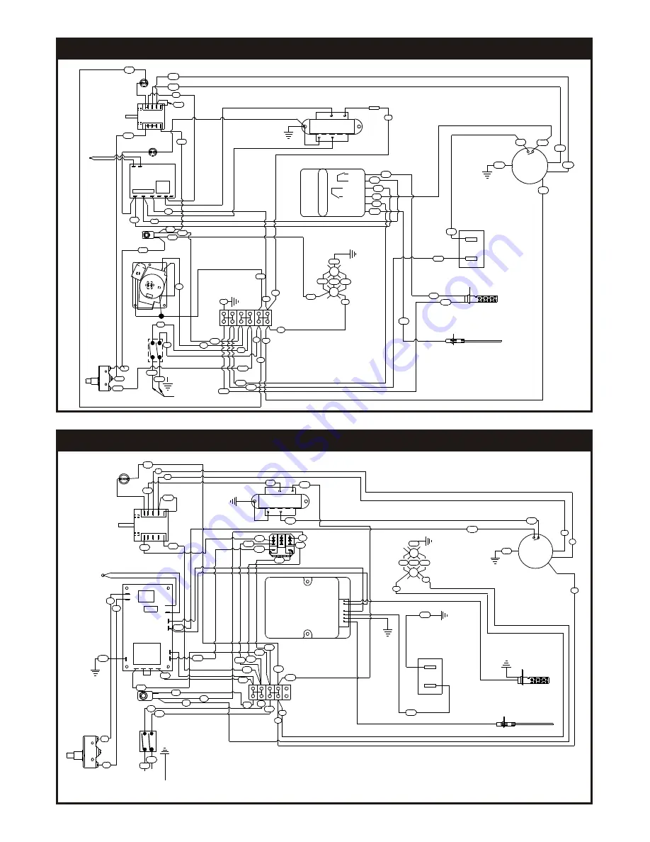
WIRING DIAGRAM - BCO-G & GDCO-G 240V, 1 PHASE   (DIAL CONTROL)

WIRING DIAGRAM - GDCO-G 240V, 1 PHASE   (PUSH-BUTTON CONTROL)

11


BLACK

P1P2P3P4

COM

NC

NO

T6 T7 T8 T9 T10T11

BLUE

YELLOW

GROUND STUD

POWER

LIGHT

T-STAT

LIGHT

SWITCH

LIGHTS

60 MIN

TIMER

POWER
SWITCH

DOOR SWITCH

FLAME SENSOR

IGNITER

HIGH

LOW

CENTRIFUGAL


SWITCH

FAN

MOTOR

COM

240V

ORANGE

GROUND

24V

4 POS

SWITCH

T-STAT LIGHT

GROUND


STUD

GROUND


STUD

PROBE

TRANSFORMER

13

12

2

32

33

15

15

2

31

33

23

22

12

7

14

1

11

3

9

4

14

5

39

36 38

16

17

32

10

4

13

28

8

29

21

18

19

37

23

COMBINATION


VALVE

31

MOT

21

16

19

20

17

18

35

29

11

20

26

34

10

1

7

3

9

BUTT


SPLICE

L1-24VAC

GROUND

FLAME


SENSE

VALVE


HOT

THERMOSTAT

IGNITOR

22

40

41

GROUND STUD

3

2

1

4

26

IG

N

IT

IO

N

C

O

N

T

R

O

L

7

6
4

3

2

1

Plug or Connection

Supplied at installation

8806658

8806660

IGNITOR

THERMOSTAT

VALVE HOT

GROUND

FLAME SENSOR

L1-24VAC

GROUND STUD

P1 P2P3 P4

T2 T3 T4 T5

T1

T8

T9

T7

T6

T12

T13

T11

T10 DOOR

SWITCH

PROBE

21

20

23

22

LIGHTS

240V

LOW

HIGH

240V

24V

PROBE

IGNITER

FLAME SENSOR

TRANSFORMER

RELAY

4


POSTION


SWITCH

DOOR SWITCH

POWER SWITCH

PUSH BUTTON

SWITCH

CH100

CONTROL

COMBINATION VALVE

GREEN


LIGHT

CENTRIFUGAL SWITCH

FAN

MOTOR

MOT

1

2

3

COM

2

1

3

29

30

30

4

6

11

18

18

15

15

26

17

17

5

4

5

6

7

8

7

8

27

28

9

10

10

9

11

12

12

13

13

14

14

16

16

19

19

32

32

25

25

24

YELLOW

BLUE

BLACK

ORANGE

29

33

33

31

34

35

Summary of Contents for Cyclone BCO-G1

Page 1: ...urces of ignition since these methods are extremely dangerous Instructions to be followed in the event you smell gas should be posted in a prominent location Obtain these instructions from your local...

Page 2: ...tallation and Use Regulations and the relevant Building Regulations IEE Regulations Detailed recommendations are contained in the British Standard Codes of Practice B S 6172 B S 5440 Part 2 and B S 68...

Page 3: ...ust be placed into the hole on top of the oven C INSTALLATION WITH CASTERS OPTIONAL Refer to Figure 4 Four casters two with wheel brakes and the mounting hardware are packed and included in the shipme...

Page 4: ...er For Natural gas use 19 mm pipe The gas pressure regulator is part of the combination valve and is adjusted to yield a pressure of 3 5 water column 9 mbar for Natural Gas If the oven is ordered for...

Page 5: ...esign and the installation of the hood conform to local municipal codes In the U K follow ventilation requirements as detailed in B S 5440 Optional direct venting not available for European community...

Page 6: ...tronic Temperature Control and Electronic Hot Surface Direct Ignition System 2 Due to increased efficiency of this oven the temperature of standard recipes may be reduced 50 F 30 C 3 Always load each...

Page 7: ...down Rotary control To cool down the oven to a lower desired temperature follow the steps detailed below 1 Open the oven doors 2 Turn Selector Switch to oven cool down position Fan will now operate an...

Page 8: ...rub cleanser on the metal in the direction of the polished lines on the metal Rubbing cleanser as gently as possible in the direction of the polished lines will not mar the finish of the stainless st...

Page 9: ...Oven Leg 2 8633515 Foot Insert Adjustable 3 8227700 Hex Hd 5 16 18 X 3 4 Bolt 5 Zn 4 8509300 Washer Flat SAE 5 16 5 8435000 Hex Nut 5 16 18 6 82447 00 Hex Hd 3 8 16 X 750 5 1 Attach four item 2 to fou...

Page 10: ...21 16 19 20 17 18 35 29 11 20 26 34 10 1 7 3 9 BUTT SPLICE L1 24VAC GROUND FLAME SENSE VALVE HOT THERMOSTAT IGNITOR 22 40 41 BUTT SPLICE GROUNDSTUD 3 2 1 4 26 IGNITION CONTROL 7 6 4 3 2 1 GROUND STUD...

Page 11: ...35 29 11 20 26 34 10 1 7 3 9 BUTT SPLICE L1 24VAC GROUND FLAME SENSE VALVE HOT THERMOSTAT IGNITOR 22 40 41 GROUND STUD 3 2 1 4 26 IGNITION CONTROL 7 6 4 3 2 1 Plug or Connection Supplied at installat...

Page 12: ...High Speed Set fan to Low Speed Flame Sensor defective Meats are well done and not browned Bake longer or raise oven temperature slightly Do not open doors to oven for long periods Oven cycles 3 times...

Page 13: ...10801 914 576 0200 914 576 0605 1 800 431 2745 www bakerspride com fax US Canada web address BAKERS PRIDE Cyclone SERIES 4 05 Note When ordering ALWAYS specify Part Model Serial Voltage Phase type of...

Page 14: ...5A KIT CONVERSION TO LP E8766A KIT CONVERSION TO NAT Part Description 1 33 0 34 5 4 12 2 3 30 8 10 11 28 29 9 32 31 27 17 26 20 19 24 7 22 18 13 25 21 14 15 16 23 39 44 45 37 47 74 73 67 50 49 40 46 4...

Page 15: ...R3165A VALVE COMBINATION NAT VALVE COMBINATION L P 1 1 48 49 50 51 52 53 54 55 56 57 58 59 60 61 62 63 64 65 66 67 68 69 70 71 72 73 74 75 76 77 78 79 80 81 82 83 84 85 86 87 88 89 90 91 92 N5019A E81...

Page 16: ...eriod of THREE MONTHS The installation of these replacement decks is the responsibility of the purchaser The extended Cyclone door warranty years 3 through 5 is a parts only warranty and does not incl...

Reviews: