background image

9

Motor

Blower 

Wheel

Set Screw (2)

Wheel Puller 

Bolt 3/8” Hex

Item 1

Item 2

Item 3

E3770A

E3771A

3/8”-16 Bolt

1. Attach  two  item  2  to  two 

item 1 using item 3, 4 and 5. 

2. Attach  two  item  7  to  two 

item 1 using item 3, 4 and 5. 

3. U s i n g   p r o p e r   l i f t i n g  

equipment attach item 1 to 
the  corresponding  hole 
patterns  located  in  the 
bottom  of  the  oven  with 
item 6. 

1

21796810 Weldment, Oven Leg 

2

8633102

Caster, 5” Swivel W/Top Plate

3

8227700

Hex Hd 5/16-18 X ¾ Bolt #5 Zn

4

8509300

Washer, Flat SAE, 5/16

5

8435000

Hex-nut 5/16-18

6

82447-00 Hex Hd. 3/8-16 X .750 #5

7

8633101

Caster, 5" Swivel W/Plate & Brake

With Plate Caster

          LEG ASSEMBLY INSTRUCTIONS - MODEL:BCO-E & GDCO-E

1

21796810 Weldment, Oven Leg

2

8633515

Foot Insert, Adjustable

3

8227700

Hex Hd 5/16-18 X 3/4 Bolt #5 Zn

4

8509300

Washer, Flat, SAE, 5/16

5

8435000

Hex-Nut 5/16-18

6

82447-00

Hex Hd. 3/8-16 X .750 #5

1. Attach four item 2 to four   


item 1 using item3, 4 & 5.

2. Using  proper  lifting 


equipment attach i t e m 1     
to the corresponding hole 
patterns located  i n   t h e  


bottom of the oven  with 


item 6. 

Without Plate Caster

Item  P/N      Description

Item

P/N

Description

 Figure 4

Figure 3

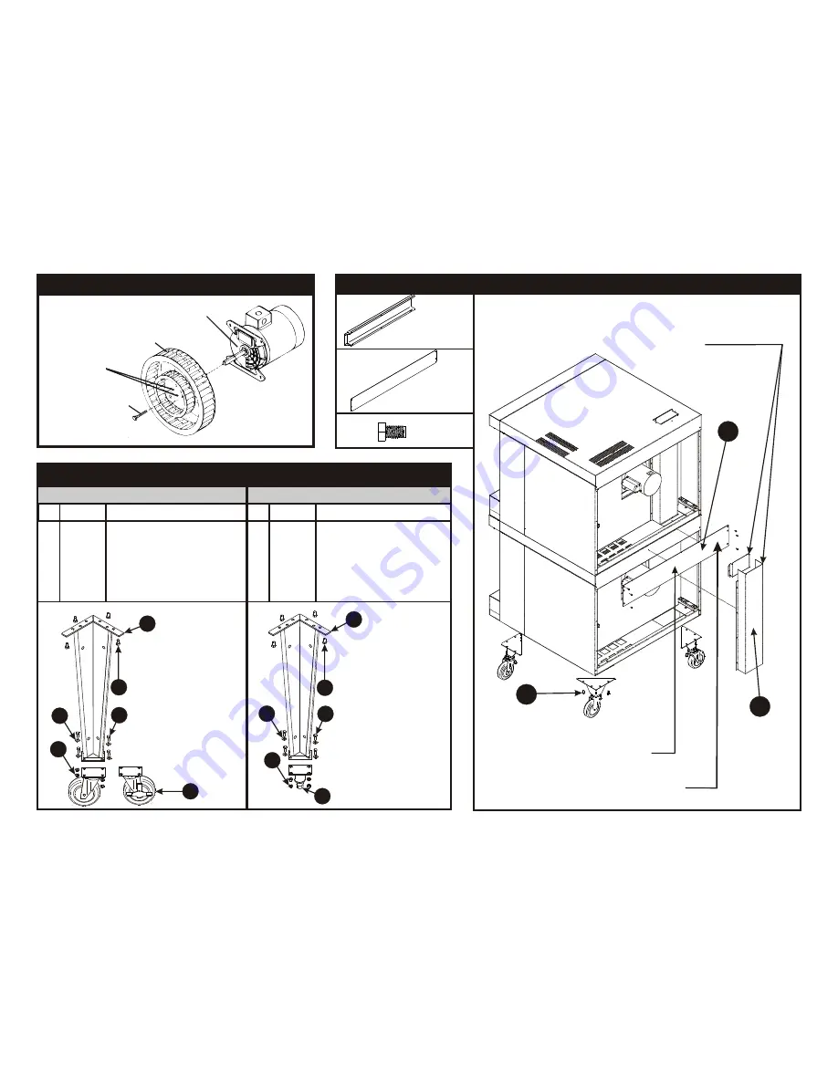
 STACKING INSTRUCTIONS FOR: BCO-G & GDCO-G CONVECTION OVENS

CLEANING THE BLOWER WHEEL

Figure 2

Attach part # 21818062 with 6 
each 8-32 stainless screws

Material: 14 ga201 Stainless

Remove  the  outer  and  inner  flue  from  the 
bottom  oven  before  placing  the  top  oven  (to 
prevent damaging the bottom oven’s flue). Re-
install after top oven is positioned.

2

1

3

22

1

77

6

44

3

55

4

66

5

33

2

22

1

77

6

44

3

55

4

66

5

88

7

Summary of Contents for Cyclone BCO-G1

Page 1: ...urces of ignition since these methods are extremely dangerous Instructions to be followed in the event you smell gas should be posted in a prominent location Obtain these instructions from your local...

Page 2: ...tallation and Use Regulations and the relevant Building Regulations IEE Regulations Detailed recommendations are contained in the British Standard Codes of Practice B S 6172 B S 5440 Part 2 and B S 68...

Page 3: ...ust be placed into the hole on top of the oven C INSTALLATION WITH CASTERS OPTIONAL Refer to Figure 4 Four casters two with wheel brakes and the mounting hardware are packed and included in the shipme...

Page 4: ...er For Natural gas use 19 mm pipe The gas pressure regulator is part of the combination valve and is adjusted to yield a pressure of 3 5 water column 9 mbar for Natural Gas If the oven is ordered for...

Page 5: ...esign and the installation of the hood conform to local municipal codes In the U K follow ventilation requirements as detailed in B S 5440 Optional direct venting not available for European community...

Page 6: ...tronic Temperature Control and Electronic Hot Surface Direct Ignition System 2 Due to increased efficiency of this oven the temperature of standard recipes may be reduced 50 F 30 C 3 Always load each...

Page 7: ...down Rotary control To cool down the oven to a lower desired temperature follow the steps detailed below 1 Open the oven doors 2 Turn Selector Switch to oven cool down position Fan will now operate an...

Page 8: ...rub cleanser on the metal in the direction of the polished lines on the metal Rubbing cleanser as gently as possible in the direction of the polished lines will not mar the finish of the stainless st...

Page 9: ...Oven Leg 2 8633515 Foot Insert Adjustable 3 8227700 Hex Hd 5 16 18 X 3 4 Bolt 5 Zn 4 8509300 Washer Flat SAE 5 16 5 8435000 Hex Nut 5 16 18 6 82447 00 Hex Hd 3 8 16 X 750 5 1 Attach four item 2 to fou...

Page 10: ...21 16 19 20 17 18 35 29 11 20 26 34 10 1 7 3 9 BUTT SPLICE L1 24VAC GROUND FLAME SENSE VALVE HOT THERMOSTAT IGNITOR 22 40 41 BUTT SPLICE GROUNDSTUD 3 2 1 4 26 IGNITION CONTROL 7 6 4 3 2 1 GROUND STUD...

Page 11: ...35 29 11 20 26 34 10 1 7 3 9 BUTT SPLICE L1 24VAC GROUND FLAME SENSE VALVE HOT THERMOSTAT IGNITOR 22 40 41 GROUND STUD 3 2 1 4 26 IGNITION CONTROL 7 6 4 3 2 1 Plug or Connection Supplied at installat...

Page 12: ...High Speed Set fan to Low Speed Flame Sensor defective Meats are well done and not browned Bake longer or raise oven temperature slightly Do not open doors to oven for long periods Oven cycles 3 times...

Page 13: ...10801 914 576 0200 914 576 0605 1 800 431 2745 www bakerspride com fax US Canada web address BAKERS PRIDE Cyclone SERIES 4 05 Note When ordering ALWAYS specify Part Model Serial Voltage Phase type of...

Page 14: ...5A KIT CONVERSION TO LP E8766A KIT CONVERSION TO NAT Part Description 1 33 0 34 5 4 12 2 3 30 8 10 11 28 29 9 32 31 27 17 26 20 19 24 7 22 18 13 25 21 14 15 16 23 39 44 45 37 47 74 73 67 50 49 40 46 4...

Page 15: ...R3165A VALVE COMBINATION NAT VALVE COMBINATION L P 1 1 48 49 50 51 52 53 54 55 56 57 58 59 60 61 62 63 64 65 66 67 68 69 70 71 72 73 74 75 76 77 78 79 80 81 82 83 84 85 86 87 88 89 90 91 92 N5019A E81...

Page 16: ...eriod of THREE MONTHS The installation of these replacement decks is the responsibility of the purchaser The extended Cyclone door warranty years 3 through 5 is a parts only warranty and does not incl...

Reviews: