background image

1

3

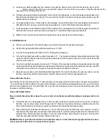
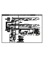
ELECTRIC WIRING DIAGRAM   EP(B,R) -8(12) -3836   208, 240 or 440-480V, 1 Ph, 2 W or 3 PH, 3 W                        

Dwg. 1048-122 7/02

Summary of Contents for EB-2-2828 Single

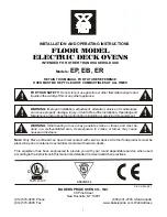
Page 1: ...he instructions in this manual and standard commercial kitchen practices WARNING Improper installation adjustment alteration service or maintenance can cause property damage injury or death Read the Installation Operating and Maintenance Instructions thoroughly before installing or servicing this equipment FOR YOUR SAFETY Do not store or use gasoline or other flammable vapors and liquids in the vi...

Page 2: ...allation of Decks 6 7 Electrical Connection 7 8 System Check 8 9 Initial Start Up 9 OPERATING INSTRUCTIONS SECTION ITEM PAGE 1 General Baking 9 2 General Baking Tips 9 3 Special Features 10 4 Cleaning 10 5 Service and Trouble Shooting 11 6 Rating Plate 11 7 Wiring Diagrams 12 15 8 Warranty 16 Attachment Parts List EP EB ER Series Large Electric Deck Ovens ...

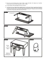
Page 3: ...separate carton complete with mounting bolts and washers Firmly bolt two legs in case of casters the two with the brakes must be used here to the upper two corners front of the oven as it rests on the pallet Note See fig 1 b Using sufficient help tilt the oven forward and lower it down so that the two front legs come to rest on the floor See fig 2 WARNING In case of casters the brakes must be firm...

Page 4: ...g 4 into the hole at the top located near the left rear corner of the oven see fig 5A Turn it to the desired direction mark the location of the holes and drill three 1 8 diameter holes then secure it with the screws supplied for that purpose This pipe is to prevent accidental closure of the vent opening by items stored on top of the oven Figure 3 BAKERS PRIDE Figure 2 Figure 1 Figure 4 Flue Divert...

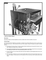
Page 5: ... internal pipe connections have been completed as per instructions below follow the instructions supplied by the manufacturer of the steam generator and the manufacturer of the steam trap for final hook up to the steam supply Stacked ovens a In all but the top oven punch four 1 1 2 diameter holes in each of the top covers utilizing the 1 8 locating holes See fig 5b b Loosen the upper pipe union s ...

Page 6: ...ck supports metal channels have to be inserted in the oven front to back flanges down and flat side up See fig 5f b Slide one slab into the bake chamber along the deck supports on the left side lower the front end carefully to avoid chipping of the deck corners then push tightly against the left oven wall c Repeat the above for the second and third slab pushing it as tightly as possible against th...

Page 7: ...35 1 and or local codes Field Connections a Remove all screws and vent knob from the control panel s Pull control panel out at the bottom then down and out from the vent rod Slip the right flange hole of the control panel back onto the vent rod then replace the vent knob to keep the control panel in an open and secure position b Remove all screws from the left access panel s then pull forward and ...

Page 8: ... contactor will be activated and the top heating elements will be energized and all should stay that way until the heat switch is turned back to 0 again or the preset temperature has been reached f Repeat d and e above with the Bottom left Heat switch The results should be the same as above except this time it will be the bottom indicator lamp the left contactor and the bottom heating elements Ove...

Page 9: ...temperature of at least 550 F 290 C Screen baking refers to baking Pizza on a screen The screen lifts the Pizza off the deck The screen may be removed near the end of the bake time to give the bottom of the Pizza a crispier crust and a darker color Bake temperatures range from 500 F 260 C to 550 F 290 C Pan baking refers to baking Pizza in pans Crusts can be thick or thin and toppings range from l...

Page 10: ...n high There is no need to reduce both at the same time If less heat is required lower the thermostat setting Optional Timer Upon request an electric timer is provided to give an audible continuous signal at the end of a preset time up to 60 minutes 72 minutes with 50Hz supply on Bake Ovens and up to 5 hours 6 hours with 50Hz supply on Roast Ovens NOTE The Timer does not control the heating elemen...

Page 11: ...cants that meet the national and or local codes DO NOT APPLY GREASE OR OIL TO SPRING LEVER SHOULDER BOLT AND SPRING ROLLER THEY HAVE SELF LUBRICATING INSERTS THAT WILLBE DAMAGED IF LUBRICATED 6 RATING PLATE Acopy of the rating plate is enclosed Please keep for future reference Attachment Parts List for EP EB and ER series floor model Electric Deck Ovens For further information and to purchase the ...

Page 12: ...12 ELECTRIC WIRING DIAGRAM EP B R 8 12 5736 208 240 or 440 480V 1 Ph 2 W or 3 PH 3 W Dwg 1048 121 7 02 3 ...

Page 13: ...13 ELECTRIC WIRING DIAGRAM EP B R 8 12 3836 208 240 or 440 480V 1 Ph 2 W or 3 PH 3 W Dwg 1048 122 7 02 ...

Page 14: ... 14 ELECTRIC WIRING DIAGRAM EP B R 8 12 5736 230 400V STAR Dwg 1048 123 7 02 ...

Page 15: ...15 ELECTRIC WIRING DIAGRAM EP B R 8 12 3836 230 400V STAR Dwg 1048 124 7 02 ...

Page 16: ...period of THREE MONTHS The installation of these replacement decks is the responsibility of the purchaser The extended Cyclone door warranty years 3 through 5 is a parts only warranty and does not include labor travel milage or any other charges EXCLUSIONS Negligence or acts of God Thermostat calibrations after 30 days from equipment installation date Air and Gas adjustments Light bulbs Glass door...

Reviews: