background image

WIRING DIAGRAMS

14

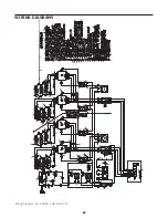
Wiring Diagram: EP-2-2828, 230-400v, 3Ph

14

-

06/01/04

GTB

CORRECT THERMOSTAT POST LABELS

A

-

-

B

C

CORRECT TERMINAL BLOCK ORIENTATION

GTB

01/16/08

CHANGE TO FUSES & 240V LAMPS

PJJ

11/06/12

-

D

REMOVED 2 TIMERS & WIRE #100

KG

6/18/13

REV

DESCRIPTION

BY

DATE

ECR

MATERIAL

SIZE

TYPE

SPEC.

FINISH

PART NUMBER

REV.

SHEET

OF

SCALE

DRAWN

APRVD.

DATE

DATE

DECIMAL-

FRACTION- ANGLE-

WHEN 

 APPEARS, DEBURR EDGE

TOLERANCE-

.XX ± .XXX ± ± ±

BEND RADIUS

SETBACK

NONE

.015

.03

.032 1

2

2

Cooking Solutions Group

"THIS PRINT IS THE CONFIDENTIAL, PROPERIETARY INFORMATION OF STANDEX CSG,dba APW 

WYOTT

"APW" RECEIPT OR POSSESSION OF DOES NOT CONVEY ANY RIGHTS TO DIVULGE,REPRODUCE, USE 

OR ALLOW OTHERS TO USE IT WITHOUT SPECIFIC WRITTEN AUTHORIZATION OF STANDEX CSG.

STOCK NUMBER

WYOTT

APW

BAKERS

PROGRAM NOTES

DIVISION

-

-

PART

 NAME

WIRE DIAGRAM 

230V-400V EP-2/EB-2, 

3PH

-

-

-

-

-

-

-

-

-

ADRIPONC

4/03/2014

-

--

P6596Q

DIAGRAM

A

E

UPDATED REDRAWN AND UPDATED TO MATCH PHYSICAL

AP

04/29/14

4808

L2

S5

30

TH

 1

49

39

35

31

75

W

AT

TS

68

54

21

33

 5

00

 W

AT

TS

41

16

L 2

H1

22

57

5

33

41

H2

39

  7

50

 W

AT

TS

H1

45

7

2

UPPER ELEMENTS

L1

1

2

1

CB

2

H1

50

72

56

19

20

L3

13

L1

45

27

58

9

62

63

69

31

20

TB

1

55

4

74

26

53

1

11

9

17

54

28

28

L2

67

S4

57

L1

TH 3

S1

26

LOW

ER OVEN

32

11

TH

RE

PH

AS

E

L1

7

1

43

2

51

29

15

14

35

10

0

66

TH 4

32

L2

L 1

71

58

 7

50

 W

AT

TS

67

14

49

24

71

21

25

64

1

53

H2

3

30

47

S2

70

23

T2

5

51

68

H1

4

27

55

24

H2

43

47

22

3

17

UPPER OVEN

TH

 2

52

 7

50

 W

AT

TS

3

16

25

23

 5

00

 W

AT

TS

29

L1

69

61

S3

L2

E

LOWER ELEMENTS

19

L2

52

34

65

34

48

50

CB

3

H2

72

18

56

18

73

61

1

48

95

96

94

97

98

 5

00

 W

AT

TS

F1

 0

.5

A

F2

 0

.5

A

99

10

0

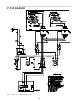
  COMPONENT LIST

CB2 - LOWER OVEN CIRCUIT BREAKER


CB3 - UPPER OVEN CIRCUIT BREAKER K1 - LOWER OVEN UPPER ELEMENT CONTACTOR  K2 - LOWER OVEN LOWER

 ELEMENT CONTACTOR 

K3 - UPPER OVEN UPPER ELEMENT CONTACTOR  K4 - UPPER OVEN LOWER ELEMENT CONTACTOR  K5 - LOWER OVEN LIMITING CONTACTOR K6 - UPPER OVEN LIMITING CONTACTOR


L1 - UPPER OVEN LAMP L2 - LOWER OVEN LAMP R1 THRU R17 - HEATER ELEMENTS S1 - MAIN POWER SWITCH S2 - LOWER OVEN UPPER ELEMENT SWITCH


S3 - LOWER OVEN LOWER ELEMENT SWITCH


S4 - UPPER OVEN UPPER ELEMENT SWITCH


S5 - UPPER OVEN LOWER ELEMENT SWITCH


T1 - LOWER OVEN TIMER T2 - UPPER OVEN TIMER TB1 - MAIN POWER TERMINAL BLOCK


TB2 - NUETRAL DISTRIBUTION TH1 - LOWER OVEN HIGH LIMIT THERMOSTAT T H2 - UPPER OVEN HIGH LIMIT THERMOSTAT  TH3 - LOWER OVEN THERMOSTAT TH4 - UPPER OVEN THERMOSTAT TR1 - STEP DOWN TRANSFORMER F1 - OVEN LIGHT FUSE F2 - OVEN LIGHT FUSE

CB

1

15

T3

T4

T2

T1

L3

L4

L2

L1

A2

A1

T3

T4

T2

T1

L3

L4

L2

L1

A2

A1

T3

T4

T2

T1

L3

L4

L2

L1

A2

A1

T3

T4

T2

T1

L3

L4

L2

L1

A2

A1

OPTIONAL

TIMER

2

3

1

TB

2

4

12

10

8

6

6

8

10

12

2

2

N

15

 7

50

 W

AT

TS

88

12

  5

00

 W

AT

TS

11

   7

50

 W

AT

TS

UPPER ELEMENTS

92

82

83

89

94

87

84

91

17

  7

50

 W

AT

TS

87

91

86

90

88

16

  7

50

 W

AT

TS

13

  5

00

 W

AT

TS

89

81

LOWER ELEMENTS

85

92

93

81

14

  5

00

 W

AT

TS

Summary of Contents for EP-2-2828 Single

Page 1: ...BUILT BY CRAFTSMEN TESTED BY TIME SERIES EP OPERATION MANUAL HEARTHBAKE SERIES COUNTERTOP ELECTRIC DECK OVENS ...

Page 2: ... Read the installation operating and maintenance instructions thoroughly before installing or servicing this equipment CAUTION Instructions to be followed in the event the user smells gas must be posted in a prominent location in the kitchen area This information shall be obtained from the local gas supplier NOTICE BAKERS PRIDE OVEN COMPANY LLC 265 Hobson St Smithville TN 37166 Phone 800 527 2100 ...

Page 3: ...o refer to the oven by the correct model number including the prefix and suffix letters and numbers and the warranty serial number The rating plate affixed to the oven contains this information IMPORTANT FOR FUTURE REFERENCE Please complete this information and retain this manual for the life of the equipment For Warranty Service and or Parts this information is required Model Number Serial Number...

Page 4: ...5 46 1168 37 5 952 43 5 1 23 E 2 2828 600 273 43 5 11058 46 1168 37 5 952 43 5 1 23 Specifications Deck Size Overall Dimensions L X W Height Number of Decks Width Depth Height Model Inches mm Inches mm Inches mm Inches mm Inches mm EP 1 2828 28x28 711x711 5 25 133 1 42 1067 33 25 845 15 75 400 EP 2 2828 28x28 711x711 5 25 133 2 42 1067 33 25 845 29 737 Dimensions Each oven requires its own supply ...

Page 5: ...d manufactured of non flammable materials The oven must be installed on a surface that is at least as large as the outer dimensions of the oven The oven must be installed with adequate clearance to combustible and non combustible walls If legs are not used the oven must be sealed to countertop with an NSF approved sealant Minimum Operating Clearances Clearances to combustible surface is 1 inch 25 ...

Page 6: ... bolt locations at each corner of the oven base 4 You will need three 3 8 16 hex head bolts and three 3 8 flat washers to mount each leg Align the leg to one of the matching bolt holes on the base and inset a bolt and washer Install the other bolts and finger tighten into place before using a wrench to fully tighten them all 5 Be sure to tighten all bolts for each leg When installing casters make ...

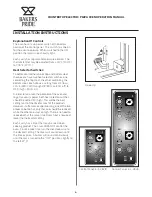
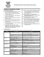
Page 7: ...ation to holes in the bottom shelf Align top hooks to cut outs in upper support bracket Lower into position 8 Align oven racks order separately to the shelf heights desired and slide into place Electrical Connections 1 Installation must be performed by licensed electrician 2 A separate electrical connection to the mains must be provided for each oven 3 An all pole disconnect must be provided by th...

Page 8: ...9 80 on 20 off to 10 high 100 on In order to maximize the potential of the oven and to get maximum power both heat selector switches should be set to 10 high This will be the best setting most of the time for most of the products However if after some experimenting one of the two proves to be too hot only that one should be reduced while the other one stays on high There is no need to reduce both ...

Page 9: ...es indicator and heating elements When oven starts to cool all functions will be restored The top and bottom heat control switches are OFF Turn switches to a position other than OFF This will allow indicator lamps contactors and heating elements to operate Power supply fuses or circuit breakers are blown or have been tripped Replace fuse or reset circuit breaker No power Power supply fuses or circ...

Page 10: ...Wipe interior surfaces with a wet cloth or light weight scouring pad Food particles or spills that accumulate on the baking hearth may be brushed off with a normal oven brush Stubborn spills should be heated to a maximum temperature for approximately one hour to burn the spill so it will crumble and easily brush out afterwards Do not use oven cleaners caustic solutions or mechanical means that may...

Page 11: ...COUNTERTOP ELECTRIC PIZZA OVEN OPERATION MANUAL 9 EXPLODED VIEW Exploded View EP 1 EP 2 2828 ...

Page 12: ...tor 240V 25A 4Pole 50 60Hz 21 M1382X Timer 60 Minute M1384X Timer 15 Minute 22 M1481X Thermostat 400 C 23 M1482X Thermostat Hi Limit 24 P1025X Ground Lug 25 P1045X Snap Bushing 2 26 C1074X Wire Clamp 27 P1098X Terminal Block 28 P1145A Light Assy 240v 15w Snap in 29 P1150A Din Rail 4 1 4 EP 1 30 P1210E Din Rail 8 1 2 EP 1 31 U4168A Manual Installation Operation 32 S1062A Terminal Cap 10 32 33 S1306...

Page 13: ...88 57 84 L1 TH 3 LOWER ELEMENTS S1 26 EP 1 LOWER OVEN 32 11 SINGLE PHASE L1 1 43 K 2 51 29 15 82 14 35 100 66 TH 4 32 L2 L 1 69 58 R 5 750 WATTS 88 67 T3 T4 T2 T1 L3 L4 L2 L1 A2 A1 89 14 R 17 750 WATTS 93 24 81 72 94 21 25 64 1 53 H2 K 3 30 47 S2 70 23 T2 50 68 91 83 H1 K 4 27 85 86 24 H2 43 49 22 3 17 UPPER OVEN TH 2 52 R 6 750 WATTS 3 16 25 23 R 3 500 WATTS 29 L1 71 61 S3 L2 R 12 500 WATTS E LOW...

Page 14: ... 88 57 84 L1 TH 3 LOWER ELEMENTS S1 26 EP 1 LOWER OVEN 32 11 THREE PHASE L1 7 1 43 K 2 51 29 15 82 14 35 100 66 TH 4 32 L2 L 1 69 58 R 5 750 WATTS 88 67 T3 T4 T2 T1 L3 L4 L2 L1 A2 A1 89 14 R 17 750 WATTS 93 49 24 81 72 94 21 25 64 1 53 H2 K 3 30 47 S2 70 23 T2 5 51 68 91 83 H1 K 4 27 55 85 86 24 H2 43 47 22 3 17 UPPER OVEN 93 TH 2 52 R 6 750 WATTS 3 16 25 23 R 3 500 WATTS 29 L1 71 61 S3 L2 R 12 50...

Page 15: ... 3 17 UPPER OVEN TH 2 52 R 6 750 WATTS 3 16 25 23 R 3 500 WATTS 29 L1 69 61 S3 L2 E LOWER ELEMENTS 19 L2 52 34 65 34 48 50 CB3 H2 72 18 56 18 73 61 1 48 95 96 94 97 98 R 2 500 WATTS F1 0 5A F2 0 5A 99 100 COMPONENT LIST CB2 LOWER OVEN CIRCUIT BREAKER CB3 UPPER OVEN CIRCUIT BREAKER K1 LOWER OVEN UPPER ELEMENT CONTACTOR K2 LOWER OVEN LOWER ELEMENT CONTACTOR K3 UPPER OVEN UPPER ELEMENT CONTACTOR K4 U...

Page 16: ...7 750 WATTS 67 14 49 24 71 21 25 64 1 53 H2 K 3 30 47 S2 70 23 T2 5 51 68 H1 K 4 27 55 24 H2 43 47 22 3 17 UPPER OVEN TH 2 52 R 6 750 WATTS 3 16 25 23 R 3 500 WATTS 29 L1 69 61 S3 L2 E LOWER ELEMENTS 19 L2 52 34 65 34 48 50 CB3 H2 72 18 56 18 73 61 1 48 95 96 94 97 98 R 2 500 WATTS F1 0 5A F2 0 5A 99 100 COMPONENT LIST CB2 LOWER OVEN CIRCUIT BREAKER CB3 UPPER OVEN CIRCUIT BREAKER K1 LOWER OVEN UPP...

Page 17: ...4 R 17 750 WATTS 93 49 24 81 72 94 21 25 64 1 53 H2 K 3 30 47 S2 70 23 T2 5 51 68 91 83 H1 K 4 27 55 85 86 24 H2 43 47 22 3 17 UPPER OVEN 93 TH 2 52 R 6 750 WATTS 3 16 25 23 R 3 500 WATTS 29 L1 71 61 S3 L2 R 12 500 WATTS E LOWER ELEMENTS 19 L2 R 15 750 WATTS 52 4 R 13 500 WATTS 34 65 34 48 87 50 CB3 87 H2 74 18 56 18 73 64 1 R 14 500 WATTS 48 95 96 94 97 98 R 2 500 WATTS F1 0 5A F2 0 5A 99 100 CB1...

Page 18: ...7 LOWER ELEMENTS 67 R 4 500 WATTS 66 64 62 63 61 72 69 73 R 6 750 WATTS R 5 750 WATTS 73 R 7 750 WATTS 74 70 71 69 72 BLACK WHITE GREEN F2 0 5A L 1 F1 0 5A T4 L4 T3 L3 T2 L2 T1 A1 A2 L1 T4 L4 T3 L3 T2 L2 T1 A1 A2 L1 COMPONENT LIST CB1 CONTROL CIRCUIT BREAKER CB2 LOWER OVEN CIRCUIT BREAKER K1 UPPER ELEMENT CONTACTOR K2 LOWER ELEMENT CONTACTOR L1 OVEN LAMP R1 THRU R7 HEATER ELEMENTS S1 MAIN POWER SW...

Page 19: ... LIST CB1 CONTROL CIRCUIT BREAKER CB2 LOWER OVEN CIRCUIT BREAKER K1 UPPER ELEMENT CONTACTOR K2 LOWER ELEMENT CONTACTOR L1 OVEN LAMP R1 THRU R7 HEATER ELEMENTS S1 MAIN POWER SWITCH S2 UPPER ELEMENT SWITCH S3 LOWER ELEMENT SWITCH TB1 MAIN POWER TERMINAL BLOCK TH1 HIGH LIMIT THERMOSTAT TH3 OVEN THERMOSTAT F1 OVEN LIGHT FUSE F2 OVEN LIGHT FUSE T1 OVEN TIMER 49 50 5 49 5 61 68 64 UPPER ELEMENTS R 1 750...

Page 20: ...8 30 28 27 TH 1 15 19 16 TH 3 21 25 27 1 1 2 15 4 25 39 39 H1 L1 H2 L2 S2 28 41 41 H1 L1 H2 L2 S3 30 16 14 13 TB1 X E Y Z 9 1 52 K 2 K 1 4 51 47 52 48 47 51 61 68 64 UPPER ELEMENTS R 1 750 WATTS R 3 500 WATTS R 2 500 WATTS 68 65 67 LOWER ELEMENTS 67 R 4 500 WATTS 66 64 62 63 61 72 73 R 6 750 WATTS R 5 750 WATTS 73 R 7 750 WATTS 74 70 71 69 72 T4 L4 T3 L3 T2 L2 T1 A1 A2 L1 T4 L4 T3 L3 T2 L2 T1 A1 A...

Page 21: ...R 2 500 WATTS 68 65 67 LOWER ELEMENTS 67 R 4 500 WATTS 66 64 62 63 61 72 73 R 6 750 WATTS R 5 750 WATTS 73 R 7 750 WATTS 74 70 71 69 72 T4 L4 T3 L3 T2 L2 T1 A1 A2 L1 T4 L4 T3 L3 T2 L2 T1 A1 A2 L1 COMPONENT LIST CB1 CONTROL CIRCUIT BREAKER CB2 LOWER OVEN CIRCUIT BREAKER K1 UPPER ELEMENT CONTACTOR K2 LOWER ELEMENT CONTACTOR L1 OVEN LAMP R1 THRU R7 HEATER ELEMENTS S1 MAIN POWER SWITCH S2 UPPER ELEMEN...

Page 22: ...and serial number of the unit needing service include the voltage or gas type Normal Business Hours 8 00 a m to 4 30 p m Central Telephone 800 264 7827 Tech Service Option 2 Email TechService partstown com www bakerspride com WARRANTY EXCLUSIONS THE FOLLOWING WILL NOT BE COVERED UNDER WARRANTY Baker s Pride sole obligation under this warranty is limited to either repair or replacement parts subjec...

Page 23: ...TANT FOR FUTURE REFERENCE Please complete this information and retain this manual for the life of the equipment For Warranty Service and or Parts this information is required Model Number Serial Number Date Purchased ...

Page 24: ... new product announcements and events on social media 265 Hobson St Smithville TN 37166 Phone 800 527 2100 bakerspride com 10 2021 Social icon Square Only use blue and or white For more details check out our Brand Guidelines ...

Reviews: