


1
●
Be sure your power voltage is same as the unit's supply voltage
before connect the power cord.
●
Be sure grounding the unit.
●
After use unit, please turn off unit and unplug.
●
Do not touch the metal parts near the tip while using.
●
Before replacing parts or storing the unit, turn the power off and allow
the unit cool down to room temperature.
●
Do not use the product near flammable items.
●
Do not modify the unit.
●
Use only genuine replacement parts.
●
Do not wet the unit or use the unit when your hands are wet.
●
The soldering process will produce smoke, so make sure the working
area is well ventilated.
CAUTION
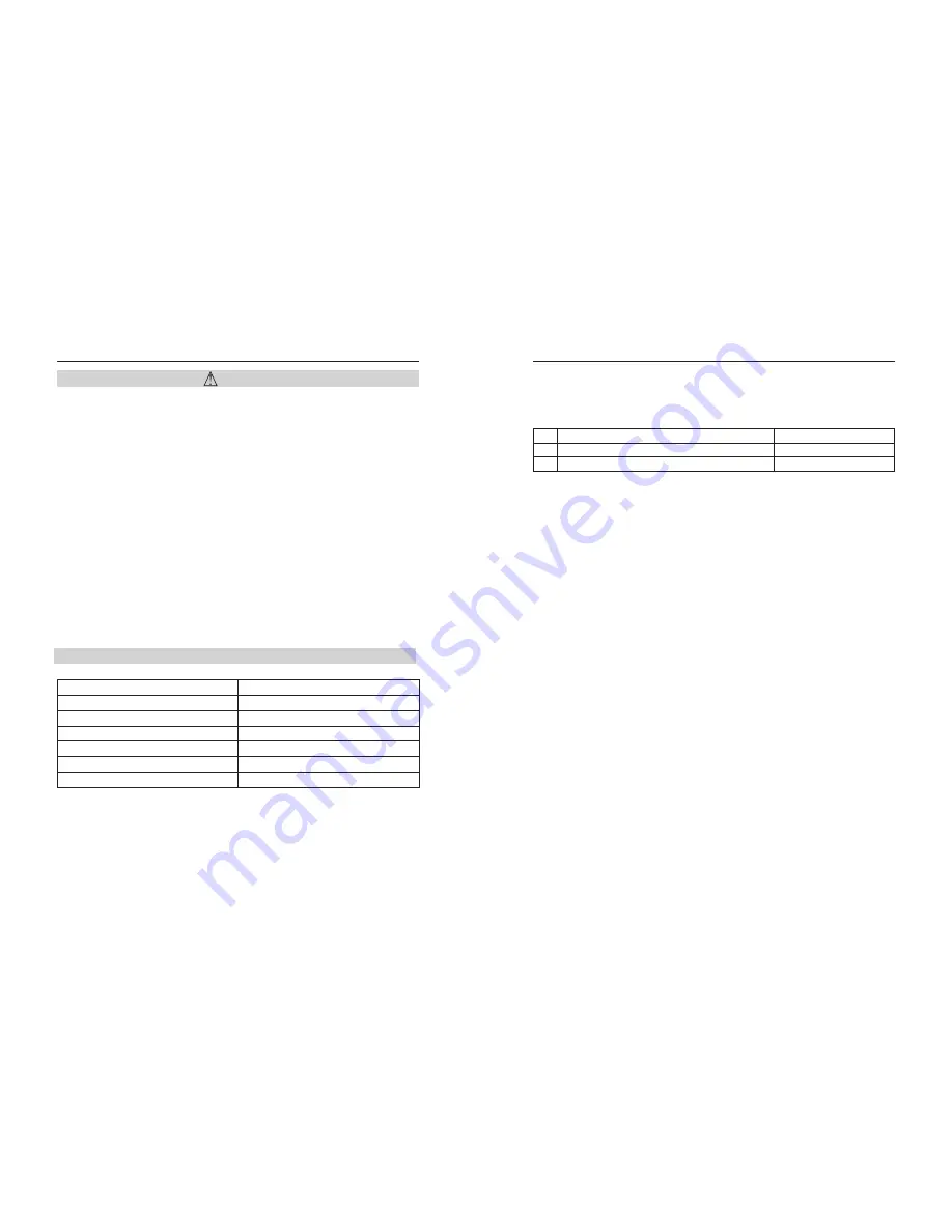
Packing List
1
1
1
1
1
1
Item
Quantity
Lead free soldering station
Iron
Iron holder (include cleaning ball)
Power cord
Grounding wire
Instruction manual
10
iron.If the resistance of “C” is bigger than the resistance value listed
below, please clean and remove the oxide with sand paper and steel wool.
Excel 2 High frequency iron resistance
A
B
C
Between pin 4 and 5(heater)
Between pin 2 and pin 3 (Sensor)
Between high frequency iron and pin 1
<
Ω(
normal
)
10
<
1
Ω(
)
normal
<
10
Ω(
normal
)
Damage of accessories of heater and sensor
Dismantle the high frequency iron
1.
Unfasten the screw anticlockwise
①
, pull out the steel jacket
②
and
soldering tip
③
2.
Unfasten the nut anticlockwise
④
,pull out the nut from the soldering
iron.
3.
Take out heating elements
⑤
and connection cord
⑾
from soldering
iron
⑧
4.
Take out the heating elements from the soldering iron with heat-
resistance pad instead of metal tool(such as pliers).
Measure the resistance of heater and sensor
Measure the resistance when the temperature of soldering element
recovers to room temperature, please refer to Excel 2.
Check after replacement
After repalcement of heating elements, please proceed with the following
items:
Measure the resistances between pin 1 and pin4/pin5, pin1and pin2/3, pin
4and pin2/3, the resistance should be ∞, if resistance is not ∞ , the heater
may touch sensor or external cover, the station won't work.
2.Measure the resistances of “a” “b” and “c” to make sure the lead is not
distorted and the grounded wire is connected correctly.
High frequency iron lead damage
Measure the power of high frequency iron as below two methods,
1.Turn on the power, Try to shake or enwind the every parts of connection
cord. If LED indicator light of heater flashes, the connection cord should
be replaced.
2.Measuer the resistance between pins of iron plug and lead wires at the
socket.Pin1-Shilding wire, Pin2,3-sensor, Pin4,5-heater.The resistance
value
should
be
0
Ω ,
the
resistance
is
over
0
Ω
or ∞, replace the
wire.
Summary of Contents for 3200
Page 2: ...Optional Tips 12 ...


