background image

Spa Side Messages

DO NOT ENTER THE WATER. If the spa water has reached 112°F, 
the display will flash “OH ”(meaning overheat). Remove the spa cover 
to cool the water. Overheating may occur if the filter cycle is set too 
long. At 110°F, the spa should reset itself. If the high-limit sensor 
detects 118°F at the heater, the spa will shut down. When the heater 
cools to 110°F, press any button to reset the spa. If the spa will not 
reset, then shut off power to the spa and call your dealer or service 
organization.

Overheat Protection (Spa is deactivated.)

Flow Switch Detection

If a pressure switch malfunctions or not adjusted properly, the display 
will show “FL ” (meaning flow). Please see page 19 & 20 for 
instructions on how to adjust the pressure switch.

If either the high-limit or water temperature sensor malfunctions, the 
display will show “SN” (meaning sensor). Contact your dealer or 
service organization. Possible defective sensor.

Open Sensor (Spa is deactivated.)

Air Lock in Plumbing System - “Bleed” the system.
Restricted Flow - 

Insure that the water shut-off valves are open and that suction 

fittings are not blocked by debris.

Dirty Filter -

 Clean or replace filter.

Low Water Level - 

Increase water level to recommended level.

Main Breaker is OFF - 

Set to On.

Sub-Panel Breaker Off - 

Set to On.

Equipment GFCI Off - 

Set to On.

Power switch in Off position - 

Set to On

.

Components not plugged in - 

Plug in components.

Power cord not plugged in - 

Plug in power cord.

Over or High Temperature Protection On - 

Refer to Spa Side Messages.

Nothing Operates

No, Low or Surging Water Flow

The following describes situations and possible solutions to common problems 
you may encounter as a spa owner.

TroubleShooting

18

SpaDepot.com

Summary of Contents for 7100B-4.0-F

Page 1: ...CS7100B F SERIES LITE LEADER Series BALBOA Operation Manual Covers the following CS series 7100B F 7109B F 7100B 4 0 F 7109B 4 0 F SpaDepot com...

Page 2: ...l being replaced you may still need to modify the plumbing to achieve proper alignment VH Series Versi Heat Heater configuration This series is designed to allow the heater to be positioned within 60...

Page 3: ...l Cords 10 Power Connection 11 Cord Connections 12 System Plug Pinouts 12 Spa Light 12 Equipment Connections 13 Circuit Board Configurations 14 System Start Up 15 Filtration Cycles 15 Spa Side Control...

Page 4: ...minal box Refer to NEC and local codes A bonding lug is provided on the control box to permit connection of a solid copper bonding conductor between this point and any equipment metal enclosures of el...

Page 5: ...hat requires proper ventilation and is intended for outdoor use only For Permanently Installed Units For Permanently Installed Units not Provided with an Internal Disconnecting Method For Units with G...

Page 6: ...ion may be installed at the electrical service panel or a separate sub panel Use copper conductors ONLY The ground must be sized following the National Electric Code Table 250 122 For Power conductor...

Page 7: ...e to add it to an open slot in the panel Option 2 shows the power from main service panel to a GFCI subpanel within line of site of the spa Note Most local codes will allow a GFCI subpanel to be a dis...

Page 8: ...ROUND BUS BAR LINE LUG 1 LINE LUG 2 INCOMING SERVICE CONDUCTORS FROM MAIN PANEL NEUTRAL GROUND TO SPA CONTROL SYSTEM LOAD LOAD NEUTRAL MUST BE CONNECTED DIRECTLY TO GFCI AS SHOWN GFCI Wiring Detail Th...

Page 9: ...Step 5 Step 6 Step 7 Step 1 Step 2 Step 3 Remove the control system from the carton and verify contents for completeness If the application is a bottom mount install then you are ready to go directly...

Page 10: ...ealing surfaces and insert the drywell into the hole Tighten the drywell nut DO NOT over tighten Insert temperature sensor into drywell and insert grommet as shown below Allow silicone to cure for 24...

Page 11: ...plug for the control system saving you hours of install time 10 30 1220 L6 30 1180 L6 The Hydro Quip Lite Leader sensor kit has been developed to offer the maximum in flexibility Unlike the tradition...

Page 12: ...Blue White Neutral Wires Crimped Together Connect input Neutral to White Wire crimped together with Blue wire Connect Line 1 to Black Wire Connect Ground to Ground Lug provided inside control box Con...

Page 13: ...Speed Red Low Speed Black Common White Ground Green Note flat sides in connector Spa Light Your control may contain a high intensity low voltage light to enhance night time use This illustration shows...

Page 14: ...high speed Pump 1 is factory configured for 120V To convert pump 1 to 240V move the red coded white wire Common from N to L2 The ozone utilizes the black wire for L1 voltage and the white wire for ne...

Page 15: ...efault Connector J1 Spaside plug Connector J20 High Limit and Temperature sensor plug While looking at the board in the above orientation the high limit plugs in to the left side of the connector and...

Page 16: ...breaker at the electrical service panel 240 volt system 9 Adjust temperature to the lowest setting 10 Press the Lights Jets switch to run the pump on high speed Allow the pump to run until you achieve...

Page 17: ...spa and the equipment system Freeze related damage is not covered by the warranty Winterizing Chemical Water Treatment Your dealer is familiar with local water conditions and which chemicals are compa...

Page 18: ...ashing and begin to display the current spa temperature Temperature range 80 F 104 F 26 0 C 40 0 C The last measured temperature is constantly displayed on the LCD Spaside Control Operation 16 Press t...

Page 19: ...either the high limit or water temperature sensor malfunctions the display will show SN meaning sensor Contact your dealer or service organization Possible defective sensor Open Sensor Spa is deactiva...

Page 20: ...breaker at service panel Low Water Flow Clean or Replace filter No Heat High Heat Filter Cycles Running Too Long Adjust filter cycles down Temperature Set Too High Adjust Set Point High Ambient Tempe...

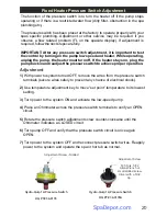
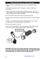
Page 21: ...stem turned OFF remove the wires from the pressure switch terminals secure wires safely to prevent any chance of electrical shock 2 Use temperature adjustment key to move set point temperature to its...

Page 22: ...witch is not closed rotate the pressure switch adjustment screw counter clockwise until the Ohmmeter indicates a CLOSED circuit 6 Re connect the heater control cord 7 Now test for proper operation of...

Page 23: ...use or care To obtain warranty service return defective products within the warranty period to Hydro Quip The Hydro Quip Limited Warranty is for service on the control box only Purchaser is responsib...

Page 24: ...85 0069C 1 Rev 01 10 18 SpaDepot com...

Reviews: