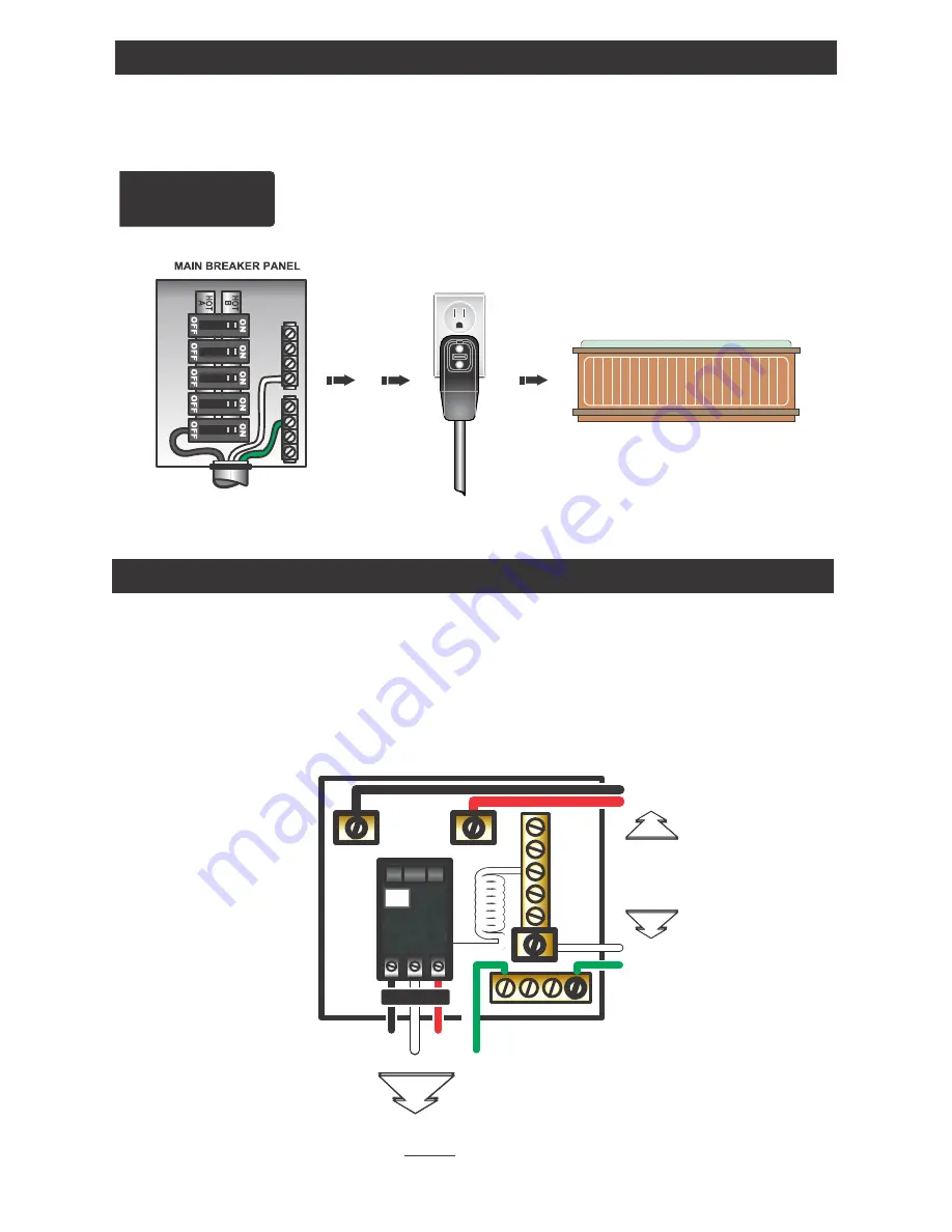
It is important that the GFCI circuit breaker is installed correctly. Often this
component has been improperly installed causing the breaker to instantly trip
when the system is turned on. Below is an illustration of a typical GFCI breaker
installation.
WARNING: Refer to the circuit breaker manufacturers installation
instructions. This illustration is meant to be a guide for Field Technicians
and is not intended to override or substitute the instructions supplied with
the circuit breaker.
GFCI
TEST
(Ground Fault Circuit Interrupter)
CIRCUIT BREAKER
NEUTRAL
PIGT
AIL
NEUTRAL
BUS BAR
LINE 1
NEUTRAL
LINE 2
GROUND
GROUND BUS BAR
LINE LUG #1
LINE LUG #2
INCOMING
SERVICE
CONDUCTORS
FROM
MAIN
PANEL
NEUTRAL
GROUND
TO SPA CONTROL SYSTEM
LOAD
LOAD NEUTRAL MUST BE CONNECTED
DIRECTLY TO GFCI AS SHOWN
GFCI Wiring Detail
This illustration depicts a typical 15 AMP, cord-end GFCI installation.
(The spa must be installed on a dedicated circuit.)
If your system was configured to include a 120VAC power cord, ensure that the proper
receptacle has been installed (a dedicated circuit is required). DO NOT under any
circumstances modify a 20 Amp plug to fit into a 15 Amp receptacle
or use an extension
cord. Doing so will create hazardous conditions and/or invalidate the warranty.
OPTION 3
15/20AMP CORD END GFCI
15A / 120V OUTLET
PORTABLE SPA
DEDICATED
Units with 15A / 20A GFCI Plug Connection
Electrical Installation
LINE 1
LINE 2
7
SpaDepot.com


