background image

Page 3

EL1500 - 40916_01_C

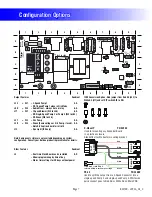
Basic System Features and Functions

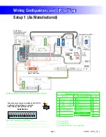
Setup 1 (As Manufactured)

s 60UMP3PEED
s 60UMP3PEED
s 60UMP3PEED
s 6"LOWER3PEED
s 6#IRC0UMP
s 6/ZONE
s 63PA,IGHT
s 6&IBER/PTIC,IGHTAND7HEEL
s 6

AV (Stereo)

s 6K7(EATER

 (EATERWATTAGEISRATEDAT67HENRUNNING6TOHEATEROUTPUTISAPPROXIMATELY

Power Requirements

s 6!#(Z!#LASS!'&#)PROTECTEDSERVICE#IRCUIT"REAKERRATING!MAX 
s ORWIRESnHOTHOTOPT NEUTRALGROUND

System Outputs

A

J6

J7

J8

J13

J44

J60

J22

1 SP. EXT. RLY

TST

AUX. F

SEN. A

SEN. B

W10

VAC

J48

J17

G

C

W7

2-SP 
EXT RLY

FUSE 20A 250V

K8

K9

F8

G

C

G

C

J20

J29

J12

J47

W2

J69

J70

W3

FUSE 3A 250V

F1

G

C

U4

K5

J71

ADCM

MAIN
PANEL

MAIN ML PNL

REMO

TE

CFG

J1

J2

J45

J82

J3

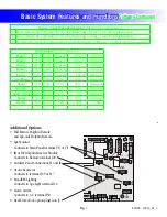
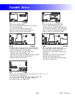
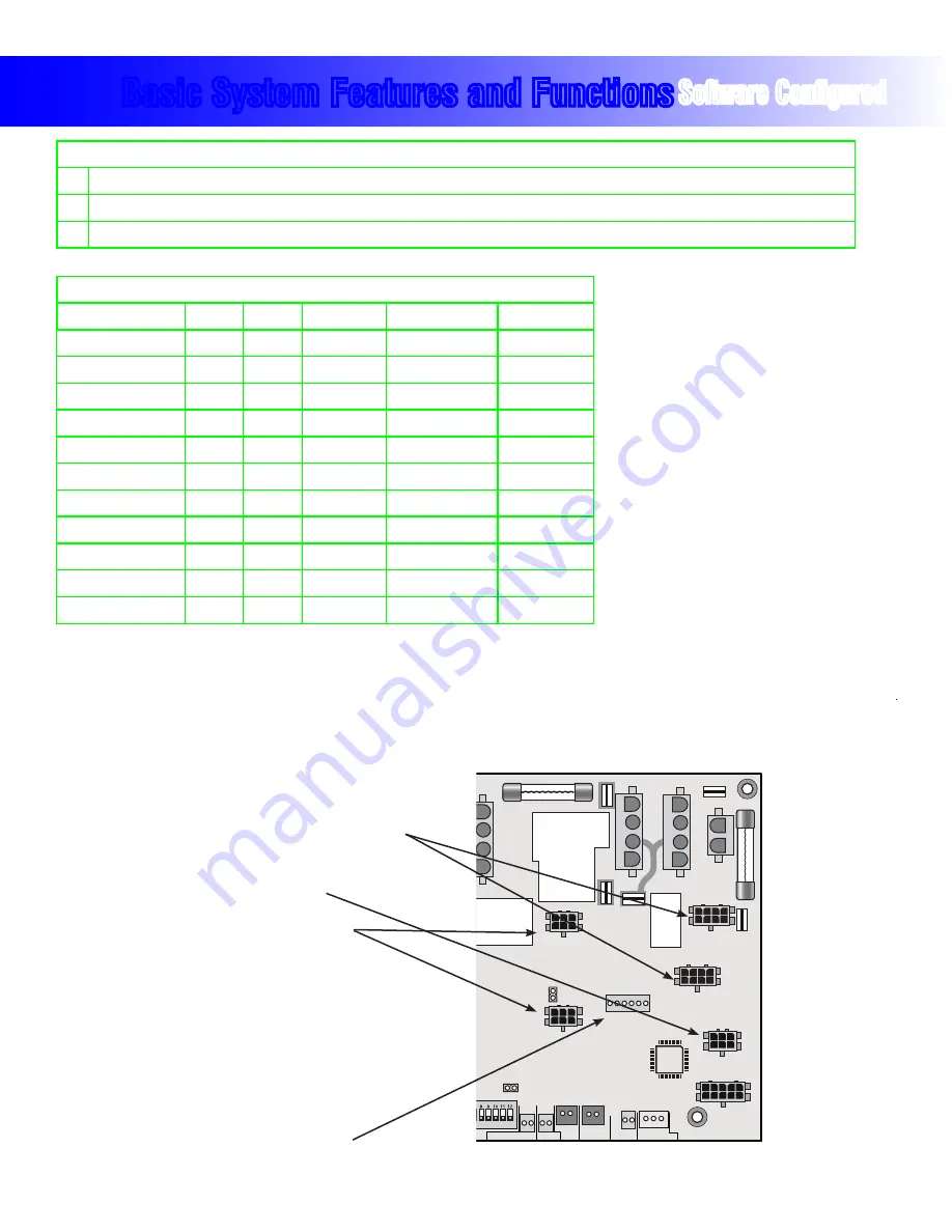
Additional Options

s &ULL&EATURE$OLPHIN2EMOTE


and Spa-only Dolphin Remote

s 3PA-ONITOR


Connects to Main Panel terminal J70 or J71

s )2OR2&$OLPHIN2ECEIVER-ODULE


Connects to Remote terminal J20

s !UXILIARY0ANEL#ONNECTIONS*AND*
s /ZONE'ENERATOR


Connects to terminal J29 or J17

s -OOD%&8,IGHTING


Connects to Spa Light terminal J12

s 3TEREO3YSTEM


Connects to A.V. terminal J50

s 2EAL4IME#LOCKOPTIONPLUGSINTO*

System Outputs

 (Circle Configurations)

Pump 1

240V

120V

1-Speed

2-Speed

Disabled

Pump 2

240V

120V

1-Speed

2-Speed

Disabled

Pump 3

240V

120V

1-Speed

N/A

Disabled

Pump 4

240V

120V

1-Speed

N/A

Disabled

Blower

240V

120V

1-Speed

___-Speed

Disabled

Circ Pump

240V

120V

N/A

N/A

Disabled

Ozone

240V

120V

N/A

N/A

Disabled

Spa Light

12V

120V

N/A

N/A

Disabled

Audio/Visual

240V

120V

N/A

N/A

Disabled

Mister

240V

120V

N/A

N/A

Disabled

Heater

240V

120V

5.5kW

4.0kW

____kW

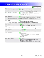
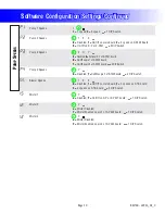
Software Configured

Service - Input Power Requirements

 (Circle Letter Assignment)

Y

6!#(Z!#LASS!'&#)PROTECTEDSERVICE#IRCUIT"REAKERRATING!MAX WIRESHOTHOTNEUTRALGROUND 

D

6!#(Z!#LASS!'&#)PROTECTEDSERVICE#IRCUIT"REAKERRATING!MAX WIRESHOTHOTNEUTRALGROUND 

Z

6!#(Z!#LASS!'&#)PROTECTEDSERVICE#IRCUIT"REAKERRATING!MAX ORWIRESHOTHOTOPT NEUTRALGROUND 

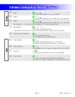
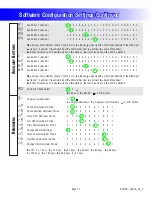
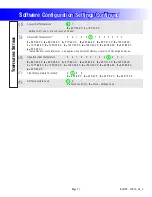
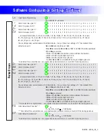
Summary of Contents for EL1500 v35

Page 1: ...Panels AX40 PN 54527 AX10 X _____________ System PN ________ System Model E2P ______ _CA_ EL1500 Tech Sheet v35 Template This is not a shippable model This document template is merely a starting point...

Page 2: ...stem PN EPN Date Requested By Changes Made This page is for listing the changes made to this system and will be filled in as the tech sheet are created updated This will provide a quick reference of w...

Page 3: ...R ODULE Connects to Remote terminal J20 s UXILIARY 0ANEL ONNECTIONS AND s ZONE ENERATOR Connects to terminal J29 or J17 s OOD 8 IGHTING Connects to Spa Light terminal J12 s 3TEREO 3YSTEM Connects to A...

Page 4: ...m For example s h would mean that the combination of how you ve set A5 and how you ve set B2 is not supported on this system s h v WOULD MEAN THAT THERE IS A PROBLEM WITH JUMPER s h would mean that th...

Page 5: ...ONE s 6 6 Stereo s 6 K7 EATER s AIN 0ANEL Switchbank A A4 Filters by Time A6 A5 A8 A9 Filter Duration 2 hr A7 A11 Special Amp Rule OFF A12 Memory ON A10 No Edit When the Logic Jumper is installed on J...

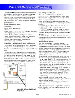
Page 6: ...y reset used when spa is powering up See Persistent Memory and Powering Up page CFE errors are illegal configurations such as a pump and a blower set to run on the same output The configuration must b...

Page 7: ...A PLASTIC ENCLOSURE 3TANDOFFS ATTACH TO HEATER MOUNTING BRACKET PN 53933 A B C D E A B C D E 1 2 3 4 5 6 7 8 9 1 2 3 4 5 6 7 8 9 TORQUE RANGE FOR TB1 27 30 IN LBS HOT BLACK NEUTRAL WHITE HOT RED K6 K1...

Page 8: ...SING OR ON THE MAIN BOARD s ONNECT WIRE ON THE 8 0 TO ON THE MAIN BOARD s ONNECT 7 ON THE 8 0 TO 2ED 6 OR 7HITE 6 ON THE MAIN BOARD AN ALSO BE USED WITH A 03 CABLE 0 TO CONTROL TWO SPEED 0UMPS PN 5513...

Page 9: ...Y Celsius 1 DIP Switch Sets default for user preferences only applies when persistent memory is reset A12 On during power up Timeouts 1 F 2 3 4 5 6 1 6 10 20 30 40 50 60 minutes F 15 minutes Pump 1 Lo...

Page 10: ...X P332 board 3 DIP Switch Pump 4 Speeds 0 Y 0 Disabled Y On Off on pin 2 of X P332 board 3 DIP Switch Blower Speeds 0 1 2 3 0 Disabled 1 On Off on main board 2 2 speeds on X TB board 3 3 speeds on X T...

Page 11: ...y is reset A12 On during power up Cleanup Cycles as User Preference n Y n Only in Configuration Settings Y Over rideable by User via User Preferences Ozone Operation A F A Operates with Heater Pump Pu...

Page 12: ...8 7 Aux Button 4 Bank B 1 2 3 4 5 6 b g F E o t d P n A U r O H 9 L 8 7 1 6 Assigns Pump Number Pump 1 Pump 2 etc b Blower g Spa Light F Fiber Optic wheel light E EitherLight o Option 1 t Mister 1 d M...

Page 13: ...0 C Sets default for user preferences only applies when persistent memory is reset A12 On during power up Uppermost Set Temperature 5 6 7 8 9 0 1 2 3 4 E F n 5 95 F 35 0 C 6 96 F 35 5 C 7 97 F 36 0 C...

Page 14: ...F g H J L n o P r Filter 1 Duration Set 2 0 1 2 3 4 5 6 7 8 9 A b C d E F g H J L n o P r Filter 2 Start Hour Set 2 0 1 2 3 4 5 6 7 8 9 A b C d E F g H J L n o P r Filter 2 Duration Set 2 0 1 2 3 4 5...

Page 15: ...s 1 5 1 5 minutes t 10 minutes Blower Purge Duration 5 1 2 3 4 6 t F 5 5 seconds 1 10 seconds 2 20 seconds 3 30 seconds 4 45 seconds 6 60 seconds 1 minute t 2 minutes F 5 minutes Mister Purge Duration...

Page 16: ...2 3 6 7 8 DOLPHIN REMOTE ROUND REMOTE Remote Button 1 Set B 1 2 3 4 5 6 b g F E o t d P n A U r O H 9 L 8 7 Remote Button 2 Set B 1 2 3 4 5 6 b g F E o t d P n A U r O H 9 L 8 7 Remote Button 3 Set B...

Page 17: ...2 3 4 8 7 6 5 Time Warm Warm Mode e Cool ML90x Custom Buttons Enable n Y n Disabled Y Enabled 1 DIP Switch ML75x MX75x Custom Button 1 1 2 3 4 5 6 b g F E o t d P n A U r O H 9 L 8 7 ML75x MX75x Custo...

Page 18: ...ch ML55x Custom Button 1 1 2 3 4 5 6 b g F E o t d P n A U r O H 9 L 8 7 ML55x Custom Button 2 1 2 3 4 5 6 b g F E o t d P n A U r O H 9 L 8 7 ML55x Custom Button 3 1 2 3 4 5 6 b g F E o t d P n A U r...

Page 19: ...ir 7 Option 5 ML400 1 2 3 ML200 3 2 1 ML260 3 2 1 ML240 3 2 1 Temp Temp Temp Temp Temp Temp Temp Temp ML40x ML2xx Custom Buttons Enable n Y n Disabled Y Enabled 1 DIP Switch Special Amperage Rule 1 2...

Page 20: ...uit board is factory configured to deliver a preset voltage 120V or 240V to the on board ozone connector J29 or J17 See the ratings table on the wiring diagram attached to the cover of the enclosure f...

Page 21: ...erminal J70 or J71 ML700 PN ______ with Overlay PN ______ s Connects to Main Panel terminal J70 or J71 Jets 3 Option Jets 1 Option Invert Blower Fiber Option Jets 1 Option Invert Blower Fiber T IME C...

Reviews: