2
GENERAL SAFETY REQUIREMENTS
NOTE: THOROUGHLY READ AND
UNDERSTAND THIS MANUAL BEFORE
I N S TA L L I N G , O P E R AT I N G , O R
SERVICING THIS EQUIPMENT.
• Please retain this instruction manual for
future reference.
• Your safety is important to us. Please read,
and follow all safety instructions listed
below.
• Some of these instructions alert you to the
potential for personal injury. “Warnings”
listed throughout this manual advise of
potential practices or procedures which may
cause damage to your equipment.
• This control handle is not designed for in-line
installation. Do not install with a shut-off
valve on the outlet side of the meter. Such
an installation could result in damage to the
meter housing.
• Ensure all operators have access to
adequate instructions about safe operating
and maintenance procedures.
• Do not exceed the maximum working
pressure of 1,500 psi.
• Do not strike the oil control gun if it fails
to operate. Refer to the “trouble shooting
guide” or return unit to your nearest Balcrank
authorized service center.
• Never allow any part of the human body
to come in contact with the control handle
outlet.
• Never point the outlet nozzle at yourself
or anyone else.
• Never exceed the pressure rating of any
component installed in the System.
• Before each use check all hoses for signs of
wear, leaks or loose fittings. Tighten all fluid
connections regularly and replace weak or
damaged hoses.
Your personal safety and
well-being are at stake.
• Before attempting any repairs or
maintenance of this product disconnect the
air supply on the pump, and release the
line pressure by pressing the lever on your
control handle.
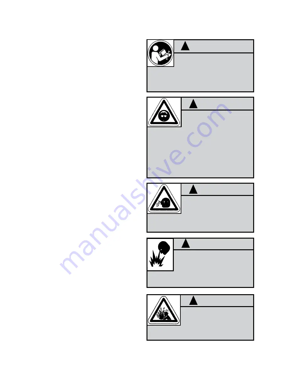
WARNING
!
DANGER: Not for use with
fluids that have a flash point
below 100°F (38°C). Examples:
gasoline, alcohol. Sparking could
result in an explosion which could result in
death.
IMPORTANT
!
Read these safety warnings and
instructions in this manual completely,
before installation and start-up of the
control handle. It is the responsibility of the purchaser
to retain this manual for reference. Failure to comply
with the recommendations stated in this manual will
damage the control handle and void factory warranty.
Before doing any maintenance on
the control handle, be certain all
pressure is completely vented from
the pump, suction, discharge, piping, and all other
openings and connections. Be certain the air supply is
locked out or made non-operational, so that it cannot
be started while work is being done on the control
handle. Be certain that approved eye protection
and protective clothing are worn at all times in the
vicinity of the control handle. Failure to follow these
recommendations may result in serious injury or
death.
WARNING
!
Airborne particles and loud
noise hazards.
Wear ear and eye protection.
WARNING
!
Manual tip cannot be used on
PGM-40 control handle. An auto
tip or semi-auto tip must be used.
Use of manual tip can result in overpressurization,
which can cause control handle to crack.
WARNING
!


