3
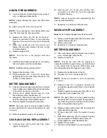
Threaded Plug
831335 Kit
(not included in
3330-037, 3330-040,
3330-071, 3330-075)
831336
O-Ring
(Included with
models prior to
5/03)
OPERATION
Use Teflon
®
tape (or suitable thread sealant)
when connecting the control handle to the hose
connection.
Press the lever on the control handle and fluid
will start flowing. The meter will now record
oil use.
The top accumulative register will record the
total volume of fluid passed through the meter.
The bottom register is a reset batch total, which
can be reset by pressing the reset button
GENERAL DESCRIPTION
This manual assists you in operating and maintaining
your new PGM-40 Mechanical Control Handle. The
information contained will help you ensure many
years of dependable performance and trouble free
operation.
Please take a few moments to read through this
manual before installing and operating your new
control handle. If you experience problems please
contact your local Balcrank
®
distributor or Balcrank
authorized service center.
OUTLET ExTENSION
The outlet extension can be fitted either inline
(forward) or on the outlet port “pistol style” located
under the meter.
Note:
The threaded plug removed from the outlet
port on the underside of the meter, is used to seal
the outlet port not in use.
SPECIFICATIONS
Accuracy . . . . . . . . . . . . . . . . . .
+- 1% (of Reading)
Flow Range . . . . . . . . . . . . . . . . . . . . . .
0.26-8 gpm
Max Operating Pressure
. . . . . . . . . . . . . .1,500 psi
Weight . . . . . . . . . . . . . . . . . . . . . . . . . . . . .2.55 lbs
Outlet: . . . . . . . . . . . . . . . . . .
3/8”NPT (prior to 5/03
. . . . . . . . . . . . . . . . . . . . . . . . .
3/8”NPS (after 5/03)
Swivel Inlet . . . . . . . . . . . . . . . . . . . . . . . .
1/2”NPT
Operating Temperature . . . . . . . . . . . . . .23
0
-122
0
F
Wetted parts . . . . . . . . . . .Aluminum, Acetal, Steel,
. . . . . . . . . . . . . . . . . . . . . . . . . . . . . . .
Nitril Rubber
Fluid Compatibility . . . . . . . . . . . .Engine Oil, Diesel
. . . . . . . . . . . . . . . . . .
Oil, ATF, Antifreeze, Gear Oil
Dimensions . . . . . . . . . . . .
10” L x 3.7” W x 4.33” H
Before maintenance or repair, shut
off the compressed air line, bleed
the pressure, and disconnect the
air line from the pump. The discharge line may be
pressurized and must be bled of its pressure.
WARNING
!
MAINTENANCE
Inspect your control handle daily for any signs
of damage. Replace any damaged parts or
components as required.
HANDLE DISASSEMBLY
Use a clean work area to carry out maintenance.
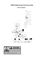
A) Remove the fluid hose from the control handle
inlet swivel (46).
B) Unscrew and remove swivel (46), washer (44),
and o-ring (45) from the control handle inlet.
Clean or replace the strainer and o-ring.
CAUTION: The swivel is under spring tension.
C) Slide off the handle sleeve (43).
D) Remove valve spring (42), seal/valve body
assembly (40, 41) and plunger (39).
LEVER AND VALVE REMOVAL
A) Using a 2.5mm allen wrench, remove the two
handle screws (38).
B) Remove lever (34).
C) Remove the washer (32) and o-ring (31), then
push the valve cam (30) from the handle body
(4), and remove o-ring (33).


