4
1. Locate or measure the length and size of your
hose in the charts below. Note how many times
you must turn the spool of the reel to properly
adjust spring tension.
Installing a Service Hose on a Bare
Reel
:
2. Place a piece of tape on the side of the spool to
help when counting the number of turns made.
3. Wearing
heavy leather gloves
, firmly grab the
outside edge of the spool with both hands. Wind
the reel to the proper number of turns, rotating
it in a clockwise direction, stopping only at the
latching locations, stop the reel where the hose
swivel is accessible and where the stop pawl is
securely latched.
1/4” I.D. x 30 ft. 11
1/4” I.D. x 40 ft. 13
1/4” I.D. x 50 ft. 15
1/4” I.D. x 60 ft. 17
3/8” I.D. x 30 ft. 12
3/8” I.D. x 40 ft. 14
3/8” I.D. x 50 ft. 16
3/8” I.D. x 60 ft. 18
High Pressure
No. of
Hose Description
Turns
Low/Med. Pressure
No. of
Hose Description
Turns
5/16” I.D. x 30 ft. 11
5/16” I.D. x 40 ft. 13
5/16” I.D. x 50 ft. 15
3/8” I.D. x 30 ft. 12
3/8” I.D. x 40 ft. 14
3/8” I.D. x 50 ft. 16
3/8” I.D. x 60 ft. 18
1/2” I.D. x 30 ft. 12
1/2” I.D. x 40 ft. 15
1/2” I.D. x 50 ft. 17
1/2” I.D. x 60 ft. 19
Installation
Tank/Wall Mounting:
The hose reel has been shipped for a ceiling mount
application unless specified differently. The outlet
arm will need to be adjusted for tank/wall mounting.
If a bare reel has been ordered see installation of
hose instructions and power spring adjustment on
following pages.
1. Select the mounting location. Be sure the
mounting structure is secure and will not tip when
reel is in operation.
2. Locate the mounting holes for drilling.
3. Adjust the outlet arm position. Before removing
the roller outlet assembly and the top tie bracket,
the power spring tension should be released
and the uprights should be secured to prevent
accidental separation. Once the outlet arm is
positioned correctly retighten bolts 80 to 90
inch pounds. (
Refer to illustrations on page 5
for further details on changing the outlet arm
position
).
4. Fasten the base using bolts of a sufficient
strength to prevent the reel from “shearing bolts”
during operation when hose is pulled.
5. Connect supply line to the inlet of hose reel.
(Low & Med. Pressure… inlet ½” NPTF & High
Pressure … inlet ¼” NPTF).
6. Install the hose stop and dispensing valve.
Position the hose stop so the hose extends far
enough for all operators to reach it.
Ceiling Mounting:
The power spring tension will need to be adjusted for
the ceiling height of the building. If a bare reel has
been ordered see installation of hose instructions and
power spring adjustment on the following pages.
1. Select the mounting location. If the ceiling is very
high, suspend a suitable support structure for the
reels, so the hoses will be long enough to reach
service area.
2. Locate the mounting holes for drilling, using
measurements on previous page. If mounting
directly to I-Beam use mounting kit 2230-013 (no
drilling required).
3. Fasten the base using bolts of a sufficient
strength to prevent the reel from “shearing bolts”
during operation when hose is pulled.
4. Connect supply line to the inlet of hose reel.
(Low & Med. Pressure… inlet ½” NPTF & High
Pressure … inlet ¼” NPTF).
5. Install the hose stop and dispensing valve.
Position the hose stop so the hose extends far
enough for all operators to reach it.
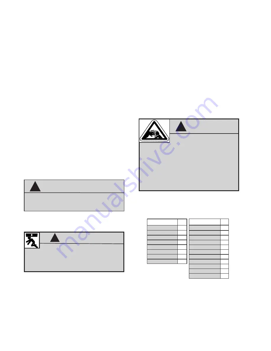
Be sure the mounting surface
is strong enough to support the reels, the
weight of the fluids and the stress caused by
hard pulls on the service hoses. See page 3
for dry weights of the hose reel assemblies.
WARNING
!
WARNING
!
The
MAXIMUM WORKING
PRESSURE
of a hose reel is determined by
the lowest rated component in the assembly.
The maximum working pressure of a hose reel
is indicated on the hose reel identification plate
located near the base of the reel.
If adding a service hose and dispensing valve to
a bare reel,
BE SURE
you know the maximum
working pressure of
ALL
components!
Do not hard pipe inlet/swivel to any existing
structure/system. Flexible connection hose must
be used to maintain swivel performance.
!
NOTE


