


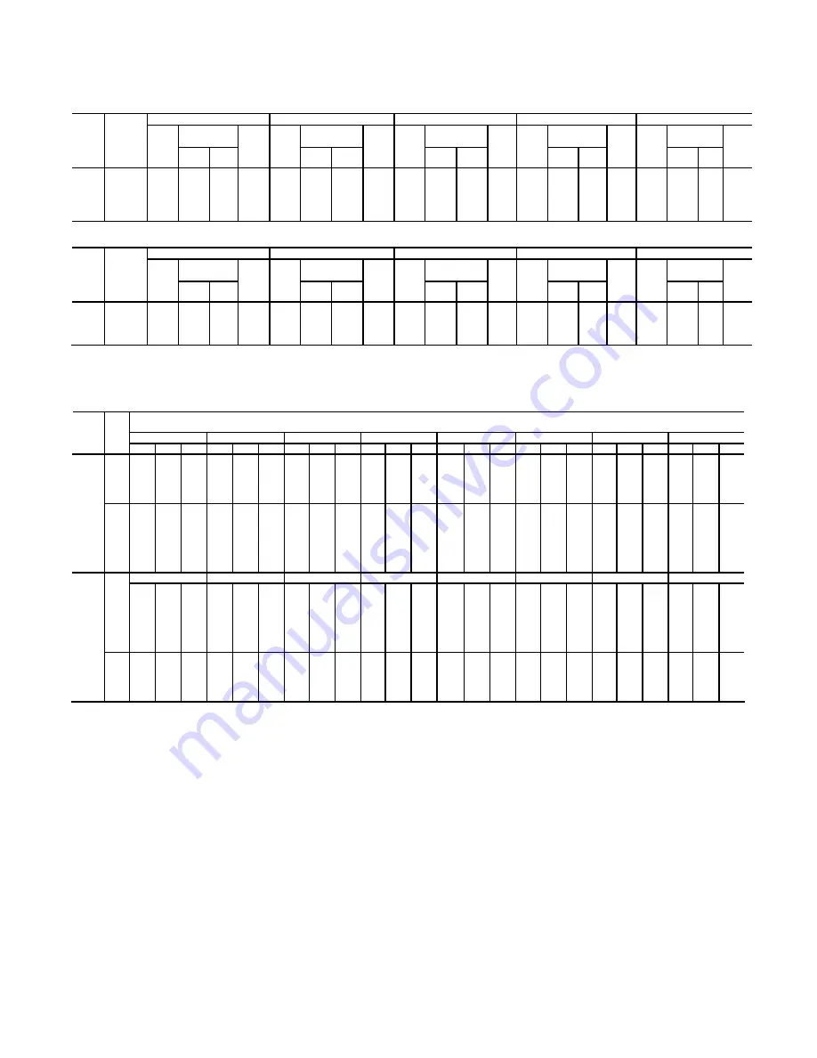
Table 1 – Flow Charge Recommendations (cont.)
Based on % of Starting Torque for 1175 RPM NEMA Design B Motors
100% @ 1175 RPM
125% @ 1160 RPM
150% @ 1150 RPM
175% @ 1130 RPM
200% @ 1100 RPM
Flow
Charge
Flow
Charge
Flow
Charge
Flow
Charge
Flow
Charge
Rated
Motor
HP
FLEXI-
DYNE
Size
Start-
ing
HP
Lbs. Oz.
Max.
Time
In
Sec.
Start-
ing
HP
Lbs. Oz.
Max.
Time
In
Sec.
Start-
ing
HP
Lbs. Oz.
Max.
Time
In
Sec.
Start-
ing
HP
Lbs. Oz.
Max.
Time
In
Sec.
Start-
ing
HP
Lbs. Oz.
Max.
Time
In
Sec.
5
9C 5.0 2 4 230
6.2 2 11 212
7.4 3 1 193
8.5 3 8
176
9.4 3 12
161
7½
9C 7.5 3 0 191 9.3 3 9 163
11.1 3 14 144
12.7 4 4 134
14.1 4 12
126
10 11C 10.0 5 0 480
12.4 5 5 439
14.8 5 10 398
17.0 6 3 360
19.0 7 0 325
15 11C 15.0 5 14 394
18.0 6 5 343
22.0 7 0 274
25.0 7 14
222
28.0 9 0
171
20 11C 20.0 6 8 308
25.0 7 14 222
30.0 8 4 136
34.0 8 13 125
38.0 9 10
113
Based on % of Starting Torque for 875 RPM NEMA Design B Motors
100% @ 875 RPM
125% @ 870 RPM
150% @ 850 RPM
175% @ 840 RPM
200% @ 820 RPM
Flow
Charge
Flow
Charge
Flow
Charge
Flow
Charge
Flow
Charge
Rated
Motor
HP
FLEXI-
DYNE
Size
Start-
ing
HP
Lbs. Oz.
Max.
Time
In
Sec.
Start-
ing
HP
Lbs. Oz.
Max.
Time
In
Sec.
Start-
ing
HP
Lbs. Oz.
Max.
Time
In
Sec.
Start-
ing
HP
Lbs. Oz.
Max.
Time
In
Sec.
Start-
ing
HP
Lbs. Oz.
Max.
Time
In
Sec.
2
9C 2.0 2 6
1000
2.5 2 2 1000
2.9 3 0 890
3.4 3 8
750
3.7 3 12
669
3
9C 3.0 3 0 862
3.7 3 8 669
4.4 4 0 475
5.0 4 6
310
5.6 4 14
297
5
11C 5.0 5 6 1000 6.2 5 14 904 7.3 6 10 816 8.4 7 0 728 9.4 7 8 648
7½ 11C 7.5 6 8 800 9.3 7 2 656
10.9 8 0 572
12.6 8 8 527
14.0 9 5 488
Table 2 – FLEXIDYNE Thermal Capacity
Maximum Allowable Acceleration Time in Seconds for
Standard Motor Speeds at Various Starting Cycles
2 Hours
1 Hour
30 Min.
15 Min.
10 Min.
5 Min.
2 Min.
1 Min.
FLEXIDYN
E
Size
Start-
ing
HP
870 1160 1750 870 1160 1750 870 1160 1750 870 1160 1750 870 1160 1750 870 1160 1750 870 1160 1750 870 1160 1750
2.5
1000 .... ....
1000 .... ....
820 .... ....
600 .... .... 425 .... ....
225 .... .... 90 .... .... 45 .... ....
5.0 310 230 .... 310 230 .... 260 230 .... 180 190 .... 140 160 .... 70 100 .... 27 42 .... 13 22 ....
9.1 220 166 .... 220 166 .... 180 166 .... 130 135 .... 100 110 .... 50 72 .... 20 29 .... 10 15 ....
10.0 .... 150 135 .... 150 135 .... 150 135 .... 120 118 ....100 100 .... 65 70 .... 26 28 .... 13 14
15.0 ....
120 76 ....
120 76 ....
120 76 ....
100 66 .... 85 58 .... 50 38 .... 21 15 .... 11 7
9C
17.5 .... 110 64 .... 110 64 .... 110 64 .... 92 55 .... 78 48 .... 47 31 .... 19 12 .... 9 6
20 .... .... 52 .... .... 52 .... .... 52 .... .... 45 .... .... 38 .... .... 25 .... .... 10 .... .... 5
25 .... .... 40 .... .... 40 .... .... 40 .... .... 35 .... .... 30 .... .... 20 .... .... 8 .... .... 4
30 .... .... 26 .... .... 26 .... .... 26 .... .... 22 .... .... 18 .... .... 12 .... .... 5 .... .... ....
35 .... .... 21 .... .... 21 .... .... 21 .... .... 18 .... .... 15 .... .... 10 .... .... 4 .... .... ....
38 .... .... 16 .... .... 16 .... .... 16 .... .... 15 .... .... 13 .... .... 9 .... .... 3 .... .... ....
2 Hours
1 Hour
30 Min.
15 Min.
10 Min.
5 Min.
2 Min.
1 Min.
870 1160 1750 870 1160 1750 870 1160 1750 870 1160 1750 870 1160 1750 870 1160 1750 870 1160 1750 870 1160 1750
5
1000 .... ....
950 .... ....
700 .... ....
450 .... .... 290 .... ....
130 .... .... 46 .... .... 21 .... ....
10 600 480 .... 560 480 .... 440 400 .... 280 270 .... 180 200 .... 80 100 .... 30 40 .... 13 20 ....
20
320
308
116
300
308
116
230
257
116
150
175 96 90
130 80 42 65 50 15 26 21 6 13 11
30 .... 136 80 .... 136 80 .... 115 80 .... 80 67 .... 60 56 .... 30 35 .... 12 14 .... 6 7
40 ....
107 44 ....
107 44 .... 89 44 .... 63 37 .... 47 32 .... 23 20 .... 9 8 .... 4 4
50 .... 78 34 .... 78 34 .... 64 34 .... 46 28 .... 35 24 .... 17 15 .... 6 6 .... 3 3
11C
60 .... .... 24 .... .... 24 .... .... 24 .... .... 20 .... .... 17 .... .... 10 .... .... 4 .... .... ....
70 .... .... 21 .... .... 21 .... .... 21 .... .... 17 .... .... 14 .... .... 9 .... .... 3 .... .... ....
80 .... .... 18 .... .... 18 .... .... 18 .... .... 15 .... .... 12 .... .... 8 .... .... .... .... .... ....
90 .... .... 16 .... .... 16 .... .... 16 .... .... 13 .... .... 11 .... .... 7 .... .... .... .... .... ....
100
....
.... 14 .... .... 14 .... .... 14 .... .... 12 .... .... 10 .... .... 6 .... .... .... .... .... ....
REPLACEMENT OF PARTS
Disassembly
:
1.
Remove drive housing mechanism from driven shaft.
2.
Remove filler plug and flow charge from FLEXIDYNE.
3.
Remove housing screws and housing cover. Remove
cover seal retainer by inserting a small pin in holes for the
drive screws and tapping on. rod to remove drive screws.
Remove cover seal.
4.
Remove screws that attach driven hub to rotor
retainer. Remove driven hub and rotor.
5.
Remove bronze bushing retainer ring and slip bronze
bushing off drive housing.
6.
Remove ball bearing snap ring and remove ball
bearing. To remove ball bearing, place 3 equal length pins
in the 3 holes thru the end of the drive housing and press
against the pins. For sizes 9 & 11 use
11
/
64
” to
3
/
16
”
diameter pins.
7.
Remove rotor retainer and seal shield.
872-4
Summary of Contents for FLEXIDYNE 11C
Page 2: ...2...


