Section 2
Installation & Operation
MN301
Installation & Operation 2-1
Use as replacement motors for equipment made in Europe requiring IEC metric frame mounting.
Available features IP55 weather proof enclosure, aluminum frame construction.
Mounting
Motor must be securely installed to a rigid foundation or mounting surface to minimize vibration and maintain
alignment between the motor and shaft load. Improper mounting may cause vibration, misalignment and
bearing damage. The standard motor base is designed for horizontal or vertical mounting.
Ventilation
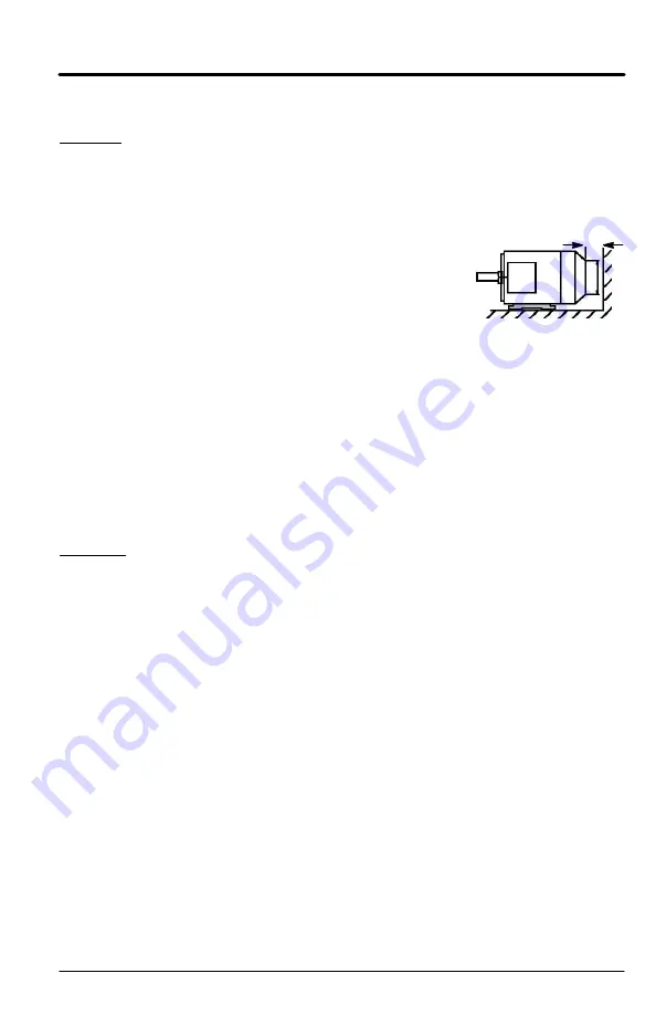
See Figure 2-1. Air intake and exhaust must be kept clean at all times.
Figure 2-1
For vertical shaft-up designs, suitable protection must be provided at the
mounting end so that no foreign objects can enter the motor air intake. Such
protection must not interfere with motor cooling and must not allow exhaust air
to re-enter the air intake.The distance between the motor air intake and wall
or other machinery must be at least 1/4 the diameter of the air intake opening.
D
> D/4
Drain Holes
Condensation drain holes must be at the lowest point of the motor. Drain holes must be kept clean.
Plug the drain holes after maintenance (draining).
Rotor Balance
Rotors are dynamically balanced with half key per DIN ISO 8821. Balance is stated on nameplate:
H or blank
means balanced with half key.
F
means balanced with full key.
N
means no key.
The coupling balance must match the type of balance for the rotor (H, F or N).
Mounting of Load
1.
Before attaching load to shaft, remove anti-corrosion paint from shaft using suitable solvent.
2.
Grease the shaft extension.
3.
Figure 2-2 illustrates mounting and removal practices that should be used.
Do not Forcibly drive the load onto the motor shaft as this will damage the bearings. If coupling is
a tight fit, heat the coupling to 80 to 100
°
C before assembly onto greased motor shaft.
Alignment
Accurate alignment of the motor with the driven equipment is extremely important. The
pulley, sprocket, or gear used in the drive should be located on the shaft as close to the shaft shoulder
as possible. It is recommended to heat the pulley, sprocket, or gear before installing on the motor shaft.
1.
Direct Coupling
For direct drive, use flexible couplings only. Mechanical vibration and roughness
during operation may indicate poor alignment. Use dial indicators to check alignment. The space
between coupling hubs should be maintained as recommended by the coupling manufacturer.
2.
End-Play Adjustment
The axial position of the motor frame with respect to its load is also
extremely important. The standard motor bearings are not designed for excessive external radial
and axial thrust loads. Improper loading will cause failure.
3.
Pulley Ratio
The best practice is to not exceed an 8:1 pulley ratio.
Caution: Do not over tension belts. Excess tension may damage the motor or driven equipment.
4.
Belt Drive
Align sheaves carefully to minimize belt wear and axial bearing loads (see End-Play
Adjustment). Belt tension should be sufficient to prevent belt slippage at rated speed and load.
However, belt slippage may occur during starting.
Motor and load must be properly aligned to prevent vibration and bearing failure. Radial and axial
alignment must be achieved and dial indicators are used to measure misalignment.
Figure 2-3 illustrates the use of dial indicators to achieve proper alignment of motor and load.
Shims motor for proper alignment. Maximum angular misalignment is 0.03 mm referred to a diameter
of 200mm. Maximum parallel misalignment is 0.03 mm. Axial clearance “E" in Figure 2-3 must exceed
coupling manufacturers specification. Recheck alignment after machine has reached operating
temperature.
Vibration
Vibration levels should be less than 3.5mm/s (at <15kW) or 4.5mm/s (at >15kW).
Conduit Box
Conduit box can be rotated 90
°
or 180
°
. Be sure that conduit box is clean and dry after
all connections are made. Be sure the box is sealed so it is dust and water tight.


