MN301
2-2 Installation & Operation
Figure 2-2
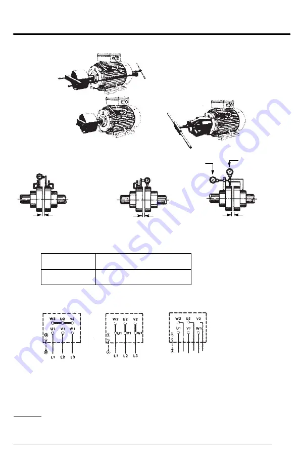
Remove
Fan Cover
Example of mounting
without female thread
Example of mounting
with female thread
Example of removal
(puller)
Figure 2-3
Angular Alignment
Parallel Alignment
(center offset)
E
E
E
Parallel
Alignment
Angular
Alignment
AC Power
Motors with flying lead construction must be properly terminated and insulated.
Connect the motor leads as shown on the connection diagram located on the name plate or inside the
cover on the conduit box. Be sure AC power is within
±
5% of rated voltage and
±
2% rated frequency.
Connection of L1, L2 and L3 to motor terminals U1, V1 and W1 determine rotation direction.
Connection of
L1, L2, L3 to
Rotation Direction
(viewed from Drive End)
U1, V1, W1
W1, V1, U1
clockwise, CW
counter-clockwise, CCW
Adjustable Frequency Power Inverters. Consult the drive instructions for maximum acceptable motor
lead lengths, and proper grounding.
Star
Delta
Star-Delta
Starter Connection
Three Phase Cage Motor Connection
Three Phase Pole Changing Motors
For pole changing motors, please observe the wiring diagram in the motor's terminal box.
Dahlander connection
The highest number of poles = high speed is shown first (AM 160 ... 4/8)
With 2 Separate Windings
The low number of poles = high speed is shown first (AM 160 ... 4/8)
Guarding
Guards must be installed for rotating parts such as couplings, pulleys, external fans, and unused shaft
extensions. This is particularly important where the parts have surface irregularities such as keys, key
ways or set screws.


