23
5 IMPORTANT APPLICATION INFORMATION
WARNING! DO NOT USE THIS DRIVE IN AN EXPLOSIVE ENVIRONMENT. AN
EXPLOSION CAN CAUSE SERIOUS OR FATAL INJURY. THIS DRIVE IS NOT EXPLOSION
PROOF.
5.1
Motor Type –
The BC-154 / BCWD140 is designed for Permanent Magnet (PM), Shunt
Wound and Universal (AC/DC) motors. Use of higher voltage motors will result in
reduction of available maximum (MAX) speed (Trimpot Adjustment). Also, if motor is not an
SCR rated type, the actual AC line amperage at full load should not exceed the motor's
DC nameplate rating.
5.2
Torque Requirements
– When replacing an AC induction motor with a DC motor and
speed control, consideration must be given to the maximum torque requirements. The full
load torque rating of the DC motor must be equal to, or greater than, that of the AC motor.
5.3
Acceleration Start –
The BC-154 / BCWD140 contains an adjustable acceleration start
feature that allows the motor to smoothly accelerate from 0-full speed over a time period of
0.5 to 4 seconds.
5.4
Limitation in Use –
The BC-154 / BCWD140 controls are designed for use on machine
applications.
CAUTION! - Be sure the BC-154 / BCWD140 is used within its maximum ratings. Follow all
installation instructions carefully
(Refer to Sections 3 and 4, on pages 15 and 16).
6 SETTING SELECTABLE JUMPERS
The BC-154 / BCWD140 has customer selectable jumpers which can be changed to
accommodate various applications.
Jumpers must be set before the control can be used.
See
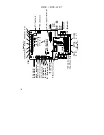
Figure 3, on page 14 for location of jumpers.
6.1
J1 - Speed and Torque Mode -
Set J1, in according to the application
requirements. Refer to Section 6.1.1.
Note: Factory setting for J1 is Speed mode.
6.1.1 Control
Mode
–
Speed
(SPD)
or Torque (TRQ).
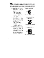
When Jumper J1 is placed in the "SPD" position the
drive will control motor speed as a linear function of
the main potentiometer setting, or analog voltage
input. The range of output speed can be adjusted
with the MIN and MAX trimpots. The motor will
maintain the preset speed as long as the maximum
load does not exceed the current limit set point. If the
motor load exceeds the current limit setting, the
Overload LED will turn on and the motor will stall.
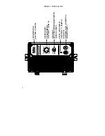
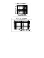
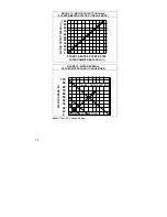
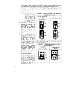
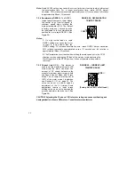
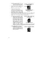
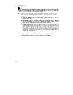
See Figure 12, Figures 13 – 16, on pages 24 and 25, which illustrate Motor Speed and
Torque Modes.
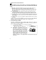
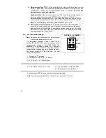
FIGURE 12 -
J1 (CONTROL MODE)
TRQ SPD
J1
Summary of Contents for NEMA-4X
Page 37: ...37 Notes...
Page 38: ...38 Notes...

