27
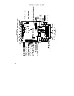
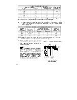
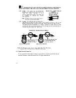
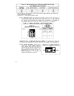
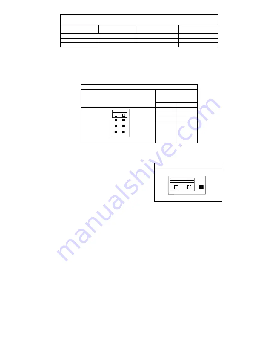
TABLE 11 - RELATIONSHIP OF AC LINE INPUT AND MOTOR VOLTAGE
with JUMPER J2 and J3 POSITION
AC INPUT
VOLTAGE
J2A, J2B POSITION
J3 POSITION**
MOTOR VOLTAGE
115 115 90
90
230 230 180 180
230 230 90* 90*
*
A 90 VDC motor can be used with a 230 VAC line. However, speed range may be reduced and
motor derating may be required.
** Position J3 to “T” if tachometer feedback is used.
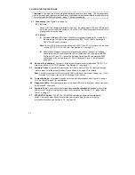
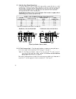
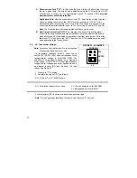
6.4 J4 – Armature Current – J4 –
Select the J4 position (2.5A, 5A, 7.5A, 10A) closest to
the rated motor current. Note that the output is factory set to 150% of the J4 position
(e.g. 15 amps in the 10A position and 11 amps in the 7.5 position, etc.). This setting can
be readjusted using the CL trimpot. See Table 12 and Section 7.2.5, on page 31.
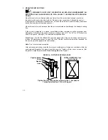
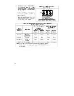
TABLE 12 - JUMPER J4 SETTING vs. MOTOR HORSEPOWER
MOTOR
HORSEPOWER
RANGE
JUMPER J4
(SHOWN IN FACTORY SETTING)
90 VDC
180 VDC
1 2
3/4
1
½
1/3 – 1/2
3/4 - 1
J4
5A
10A
7.5A
2.5A
1/6 – 1/4
1/3 – 1/2
Application Note – Subfractional Horsepower Motors.
For subfractional horsepower
motors with current ratings below 2.5 amps, the drive can be modified. Refer to Appendix A.
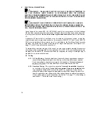
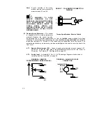
6.5 J5 – Current Limit Mode –
(Factory set for
"TCL"
) This control contains electronic
current limiting which limits the maximum
DC current to the motor (the current limit set
point is established with the selection of the
J5
position
and the setting of the CL
trimpot).
See
Figure
19. Two modes of
current limit operation are provided:
FIGURE 19 - J5 JUMPER POSITION
NTCL
TCL
J5
Summary of Contents for NEMA-4X
Page 37: ...37 Notes...
Page 38: ...38 Notes...

