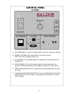
CONTROL PANEL
For the K5000/K5000E Units
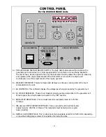
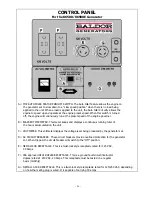
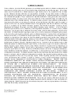
A = THE AUTO IDLER FEATURE ON/OFF SWITCH. The Auto Idler feature allows the engine on the
generator set to slow down to a "slow speed position" when there is no load being applied to
the unit. When a load is applied to the unit, the Auto Idler Circuitry allows the engine to speed up
and operate at the engine preset speed. When this switch is turned off, the engine will
continuously run at the preset speed of the engine governor.
B = ELAPSED TIME METER. This meter keeps and displays a continuous running total of the hours
accumulated on the unit.
C = AC VOLTMETER. This voltmeter displays the voltage level being produced by the generator set.
D = AC CIRCUIT BREAKERS. These circuit breakers provide overload protection for the generator set.
When tripped, the circuit breaker will switch to the "Off" position.
E = NEMA L530R RECEPTACLE. This is a twist-lock style receptacle rated for 125 VAC,
30 Amps.
F = CSA approved GFCI DUPLEX RECEPTACLE. This is a ground fault circuit interrupter
duplex rated at 250 VAC, 20 Amps. This receptacle must be tested on a regular
basis (monthly).
G = NEMA L14-30R RECEPTACLE. This is a twist-lock style receptacle rated for 125/250 VAC, depending
on how the mating plug is wired. It is capable of carrying 30 amps.
-
1
5 -
Summary of Contents for Premier 'K'
Page 24: ...K3000 Wiring Diagram 17...
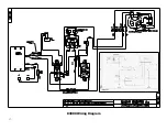
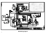
Page 25: ...K5000 Wiring Diagram 18...
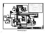
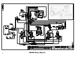
Page 26: ...K5000E Wiring Diagram 19...
Page 27: ...K6500 Wiring Diagram 20...
Page 28: ...K6500E Wiring Diagram 21...
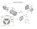
Page 29: ...Generator End Componentry 22...
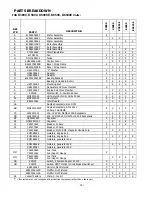
Page 30: ...CONTROL BOX COMPONENTRY 23...

