background image

CONNECTIONS 


WIRING:

  Use sufficiently large insulated wire to connect the generator set to the load. The gauge of the 

wire will depend largely on the distance, the permissible voltage drop, and the size and type of load. 

If 

you are not sure of the gauge wire needed for your application, consult a competent electrician.


FRAYED, CUT, BROKEN, LOOSELY CONNECTED, OR IMPROPERLY 
SIZED POWER CORDS OR WIRES CAN CAUSE EQUIPMENT DAMAGE, 
FIRE, SEVERE INJURY OR DEATH. INSPECT AND MAINTAIN ALL 
POWER CORDS ON A REGULAR BASIS. 


GROUNDING:

  If grounding is necessary in your application according to National Electric Code and/or 

local codes, drive a 3/4" or 1" pipe into the ground as close to the generator 
Set as is possible. This pipe must penetrate moist earth (minimum of 8 feet). Connect a ground clamp to 
this pipe and run a No. 10 wire or larger from it to the ground stud on the generator set. 
 
Do not connect the ground wire from the generator set to a water pipe or a ground used by a radio 
system. 
 

IMPROPER GROUNDING CAN CAUSE EQUIPMENT DAMAGE, SEVERE 
INJURY OR DEATH. INSPECT AND MAINTAIN THE GROUNDING 
SYSTEM IN ACCORDANCE WITH ALL APPLICABLE CODES. 

 
CONNECTIONS TO HOUSE WIRING: 

 Any electrical generator that is temporarily connected to a 

building or home (where the building is also supplied electricity by a local utility) shall be connected 

only 

by a competent electrician and only after the main service entrance switch has been disconnected and 
locked open

. This will isolate the building's electrical system from the local utility's electrical transmission 

wires and prevent the hazard of electrical back-feed to utility service workers. 
 
Any generator set that is permanently connected to a building or home (where the building is also 
supplied electricity by a local utility) shall be connected only by means of a double- throw transfer switch. 
This will isolate the building's electrical system from the local utility's electrical transmission wires and 
prevent the hazard of electrical back-feed to utility service workers. 
 

DO NOT CONNECT THIS GENERATOR SET TO ANY BUILDING'S ELECTRICAL 
SYSTEM UNLESS YOU USE AN APPROVED TRANSFER SWITCH OR THE MAIN 
SERVICE ENTRANCE SWITCH HAS BEEN DISCONNECTED AND LOCKED OPEN. 


ANY TEMPORARY OR PERMANENT WIRING CONNECTIONS MADE BETWEEN A 
GENERATOR SET AND AN EXISTING ELECTRICAL SYSTEM MUST ONLY BE 
DONE BY A QUALIFIED COMPETENT ELECTRICIAN. IMPROPER WIRING/ 
CONNECTIONS COULD CAUSE EQUIPMENT DAMAGE, PROPERTY DAMAGE, 
INJURY OR DEATH. 


CHECK ALL NATIONAL ELECTRIC CODES AND ALL LOCAL CODES IN REGARDS TO YOUR SPECIFIC 

APPLICATION. ANY NATIONAL ELECTRIC CODE OR LOCAL CODE WILL TAKE PRECEDENCE OVER ANY

OF OUR GUIDELINES OR RECOMMENDATIONS. 


- 2 -


Summary of Contents for Premier 'K'

Page 1: ...OPERATOR S MANUAL FOR YOUR PREMIER K SERIES GENERATOR BALDOR GENERATORS 3815 OREGON STREET OSHKOSH WI 54902 Phone 920 236 4200 Fax 920 236 4219 Toll Free 800 872 7697...

Page 2: ...your generator set inspect it closely for shipping damage If you find some damage notify the transportation company immediately and file a freight damage claim Think of this manual as a tool to help...

Page 3: ...es are not normally lethal an involuntary jerk of the hand caused by a hot surface or by an electrical shock can result in injury Repair of electrical generating equipment requires specialized skills...

Page 4: ...le under the influence of alcohol drugs or medication When transporting or using a generator set with the wheel option secure the unit to prevent it from moving around Do not tamper with or change the...

Page 5: ...RATOR SETS Operate the generator set on a level surface If the generator set is tilted fuel spillage may result Handle fuel with care It is highly flammable Use only clean properly marked and approved...

Page 6: ...e generator set free of grass leaves and excessive grease and oils Allow the generator set to cool before transporting it or storing it indoors Have fire extinguisher accessible and nearby while opera...

Page 7: ...tric Motor Loads 7 Parts and Service Information 8 Operation 9 Simple Troubleshooting 11 Control Panel for K3000 14 Control Panel for K5000 K5000E 15 Control Panel for K6500 K6500E 16 Wiring Diagram K...

Page 8: ...All engines give off considerable heat when running Since the engine and your generator set uses air to keep it cool it is important that the temperature of the area in which it is located is does not...

Page 9: ...r home where the building is also supplied electricity by a local utility shall be connected only by a competent electrician and only after the main service entrance switch has been disconnected and l...

Page 10: ...on the hot surfaces Always shut the engine off and allow it to cool down before refueling it SPILLED FUEL MAY IGNITE AND CAUSE PROPERTY DAMAGE SEVERE INJURY OR EVEN DEATH IF IT WOULD COME INTO CONTAC...

Page 11: ...Do not use sprayed water or compressed air to clean the generator set INSPECTING Inspect the external wires of the generator set for cuts fraying or loose connections Repair or replace any problems pr...

Page 12: ...D SPARK PLUG SHOULD ALSO BE DISCONNECTED PRIOR TO PERFORMING MAINTENANCE This manual contains only very minimal engine maintenance instructions You should refer to the engine manufacturer s owner s ma...

Page 13: ...nnect and remove the battery if your generator set is so equipped 3 Drain the used oil from the engine s crankcase and refill it with fresh clean oil if your engine is diesel proceed to step 4 4 If yo...

Page 14: ...apacitor type motor or the split phase type motor The other factors that influence the amount of current needed to start a motor are 1 The type of load connected to the motor If the electric motor is...

Page 15: ...r if known 4 Quantity of parts NOTE Engine parts can usually be obtained from a local representative of your engine manufacturer via the information in the engine manufacturer s Owner s Manual Baldor...

Page 16: ...add if necessary NEVER REFUEL THE GENERATOR SET WHEN IT IS HOT OR RUNNING 5 Open the fuel valve on the fuel tank 6 If the engine is equipped with a fuel valve open it at this time 7 Check the fuel sy...

Page 17: ...2 Either push the engine s start switch or turn the key switch fully clockwise to engage the electric start motor 3 Do not allow the starter motor to crank for more than 10 seconds at a time 4 Allow...

Page 18: ...no output voltage Make sure the generator is turning at the speed on the nameplate 2 Broken wires or loose connections Broken wires or loose connections can cause the generator set to have low or no o...

Page 19: ...attery across the capacitor longer than a fraction of a second may damage the windings of the generator Stop the unit after doing this and replace the end cover If you still have no output look for ot...

Page 20: ...nor and the Auto Idler follow these steps A Turn the Auto Idler switch OFF and start the engine B Adjust the engine for the speed specified on the generator set s nameplate C Turn the Idler Switch ON...

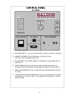
Page 21: ...level being produced by the generator set D CIRCUIT BREAKER This circuit breaker provides overload protection for the generator set When tripped the circuit breaker will switch to the Off position E...

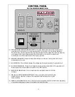
Page 22: ...running total of the hours accumulated on the unit C AC VOLTMETER This voltmeter displays the voltage level being produced by the generator set D AC CIRCUIT BREAKERS These circuit breakers provide ove...

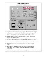
Page 23: ...ous running total of the hours accumulated on the unit C VOLTMETER This voltmeter displays the voltage level being produced by the generator set D AC CIRCUIT BREAKERS These circuit breakers provide ov...

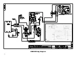
Page 24: ...K3000 Wiring Diagram 17...

Page 25: ...K5000 Wiring Diagram 18...

Page 26: ...K5000E Wiring Diagram 19...

Page 27: ...K6500 Wiring Diagram 20...

Page 28: ...K6500E Wiring Diagram 21...

Page 29: ...Generator End Componentry 22...

Page 30: ...CONTROL BOX COMPONENTRY 23...

Page 31: ...meter X X X X X X EB1242A00 Idler Module X X X X X AA Duplex Receptacle Non GFCI BB WD1541A33SP Duplex Receptacle GFCI 250V 20 Amp CSA NEMA X X X X X CC WD1541A10 30A 125 VAC NEMA L530R Receptacle X X...

Page 32: ...the reinstallation of the Baldor product upon its return to the party requiring warranty service Customers who are unable to take or ship the Baldor product to a Baldor Generator repair facility or wh...

Page 33: ...ty Policy Warranty registration within 30 days of purchase is required for portable and towable products to qualify for any warranty consideration Proof of purchase date serial number and model number...

Page 34: ...and the conditions under which it has to operate Some applications are very often used in dusty or dirty conditions which can cause what appears to be excessive wear Such wear when caused by dirt dust...

Page 35: ...ia to cause cancer birth defects and other reproductive harm CALIFORNIA PROPOSITION 65 WARNING Diesel engine exhaust and some constituents are known to the state of California to cause cancer birth de...

Page 36: ...Service is just a phone call away 800 872 7697 www baldor com products generators asp 3815 Oregon Street Oshkosh WI 54902 Phone 920 236 4200 Fax 920 236 4219...

Reviews: