1-4 Introduction
MN766
The control is now ready for use in the keypad mode. If a different operating mode is desired, refer to Chapter 5 Operating
Modes and Chapter 6 and 7 for Programming and Operation.
For more advanced tuning of the drive speed loop once coupled to the load, see “Speed Loop Tune” in “Autotune Block” in
Chapter 7.
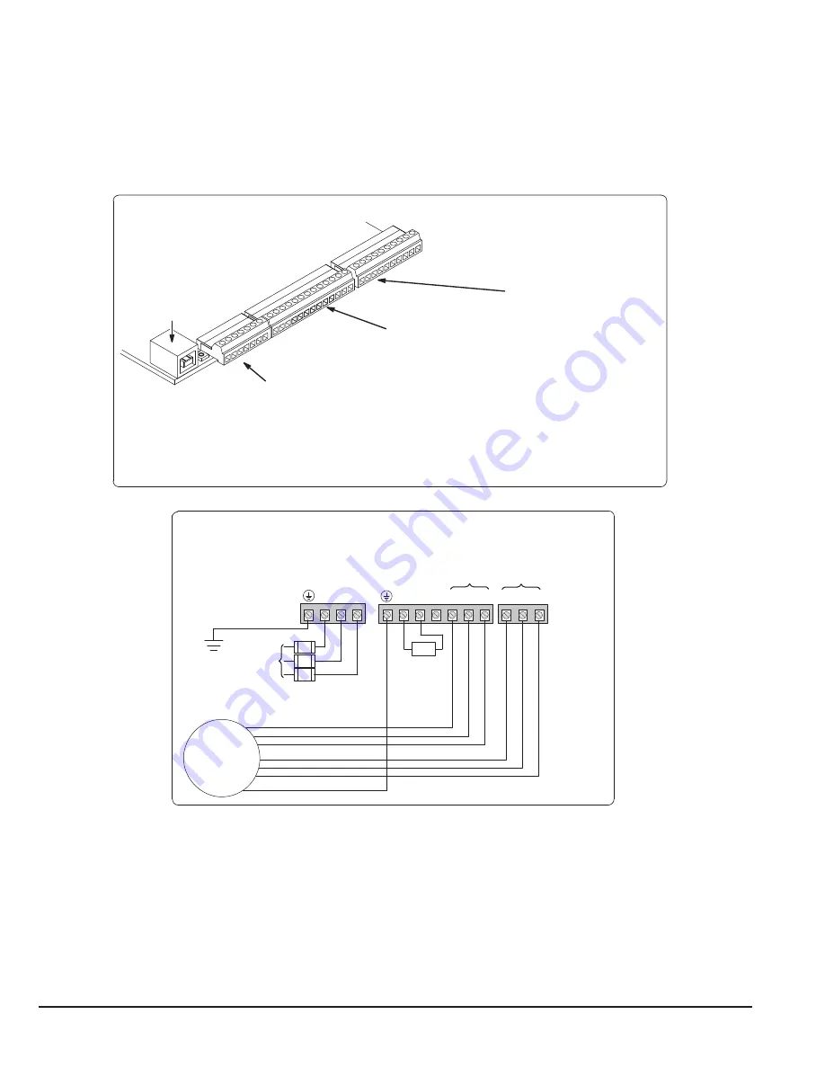
Figure 1-1 Minimum Connection Diagram
Example of Terminal Strip Layout
**
Input AC
Power
Earth Ground
DB Resistor
(Internal)
GND
TH2
TH1
T3
T2
T1
B-
R2
R1/B+
L3
L2
L1
G
T3
T2
T1
TH2
TH1
Motor
Motor Leads Motor Thermal Leads*
Fuses
AC Power & Motor Connections
Minimum Signal Connections
Terminals 1 to 7 (J1)
1 User Analog Return
2 Analog Input #1
3 Analog Ref. Power
4 Analog Input #2 +
5 Analog Input #2 -
6 Analog Output #1
7 Analog Output #2
Terminals 8 to 20 (J2)
8 Enable Input
9 Digital Input #1
10 Digital Input #2
11 Digital Input #3
12 Digital Input #4
13 Digital Input #5
14 Digital Input #6
15 Digital Input #7
16 Digital Input #8
17 Digital Out #1+ (Collector)
18 Digital Out #1- (Emitter)
19 Digital Out #2+ (Collector)
20 Digital Out #2- (Emitter)
For keypad operation, only Enable (J2-8) is required.
J1
J2
J3
USB Port
1
8
21
Terminals 21 to 30 (J3)
21 External User +24V Return
22 External User +24V
23 In24V
24 In24V Return
25 Relay Out 1 NC
26 Relay Out 1 COM
27 Relay Out 1 NO
28 Relay Out 2 NC
29 Relay Out 2 COM
30 Relay Out 2 NO
GND
Note:
The control enable input must be active to allow operation. Therefore, J2-8 Enable is connected by a factory installed
jumper to J3-24. This uses the internal supply and provides an active low at J2-8.
Remove TH1 and TH2 jumper and connect Motor Thermal Leads.
Note:
Motor thermal leads must be run in a separate conduit from motor power leads.
Note:
An open circuit on these terminals will generate a motor overtemperature fault. Refer to the fault / troubleshooting
information provided in Chapter 9.
See Figure 4-3 for terminal arrangement for the various frame sizes.
Summary of Contents for VS1SD
Page 1: ...05 13 Installation Operating Manual MN766 VS1SD AC Servo Control...
Page 12: ...2 2 General Information MN766...
Page 16: ...3 4 Installing the Drive MN766...
Page 108: ...7 34 Parameter Descriptions MN766...
Page 114: ...8 6 Customizing Your Application MN766...
Page 128: ...9 14 Troubleshooting MN766...
Page 154: ...12 12 Monitor and RTC Description MN766...


