Power Wiring 4-13
MN766
4.15 Resolver Installation
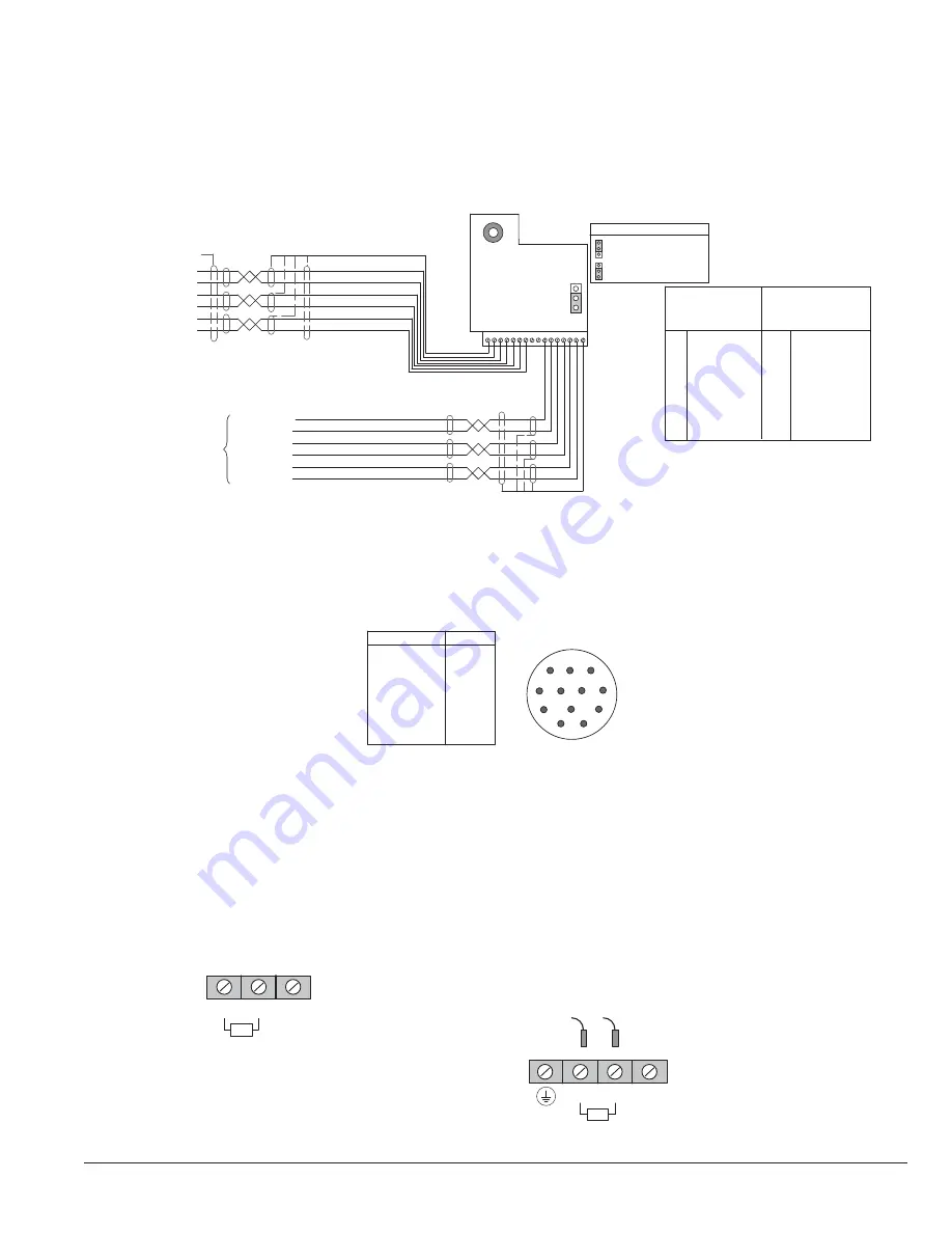
The Resolver Board is installed in the Feedback Module Slot 3. Connect resolver wiring to the resolver board as shown in
Figure 4-13. Use 16AWG (1.31mm
2
) maximum.
Figure 4-13 Resolver Connections
Sine+
Sine-
Cosine-
Exc
Excitation-
Encoder
Output
16-22A WG Twisted Pair
1
Chassis
GND
Channel A+
Channel A-
Channel B+
Channel B-
Channel C+
Channel C-
16 = Outer
Shield
Resolver
Board
16-22A WG
Twisted Pair
1
2
Sine +
3
Sine -
4
5
Cosine -
6
Exci
7
Excitation -
8
Ext Index +
9
Ext Index -
10
11
12
13
14
15
16 Δ
Resolver Input
Signal Terminals
Motor Frame
J3
1
J3 Index Source Select
Internal Index (sync)
External Index (sync)
Blue
Red
Yellow
Green
Gray
Pink
Shield
See recommended tightening torques in Table A-2.
Emulated Encoder
Output Signal
Terminals
CH A+
CH A-
CH B+
CH B-
CH C+
CH C-
Outer Shield
(Chassis GND)
Chassis GND
Δ
Δ Terminals 1 and 16 are connected internally.
4.15.1 Feedback Termination
Connections for Feedback cables are different for each type of feedback device. Standard devices are: Resolver, Halls
(Hall Effect). Custom feedback devices are also available. Request a wiring diagram of your feedback device from the
manufacturer to determine the pin-out and/or wire color codes.
Figure 4-14 Typical Connections to Feedback Termination
Resolver
Function
R1
REF HI
R2 REF
LO
S1 COS+
S3 COS-
S2 SINE+
S4 SINE-
Open
8
9
1
7
12
10
2
6
11
3
5
4
12 Pin
1
2
3
4
5
6
7-12
Pin
4.16 Optional Dynamic Brake Hardware
Refer to Figure 4-15 for DB resistor connections. Dynamic Brake (DB) Hardware must be installed on a fl at, non-fl ammable,
vertical surface for effective cooling and operation.
CAUTION:
Before external Dynamic Brake Hardware is added, the internal resistor must be disconnected
(frames AA, B, C, and D). Remove the resistor from the B+/R1 and R2 terminals. The external
resistor can be connected across these terminals. Failure to remove the internal resistor will
decrease the total resistance (parallel connection) and cause damage.
Figure 4-15 DB Terminal Identifi cation
“E” or “W” suffix
B+ / R1
R2
Frame C Size Only - Disconnect Internal DB resistor
wires from DBR1 and DBR2 terminals before
connecting external DB Resistor to prevent damage.
B+ / R1
R2
B -
DBR2
DBR1
TB101
External
External
See recommended tightening torques in Table A-2.
Frame AA, B and D Sizes
B -
Wires from the Internal Dynamic Brake resistor
for size AA, B and D controls must be removed
before external resistor hardware is installed.
Note: Although not shown, metal conduit should be
used to shield all power wires and motor leads.
Summary of Contents for VS1SD
Page 1: ...05 13 Installation Operating Manual MN766 VS1SD AC Servo Control...
Page 12: ...2 2 General Information MN766...
Page 16: ...3 4 Installing the Drive MN766...
Page 108: ...7 34 Parameter Descriptions MN766...
Page 114: ...8 6 Customizing Your Application MN766...
Page 128: ...9 14 Troubleshooting MN766...
Page 154: ...12 12 Monitor and RTC Description MN766...


