background image


EN


17 

• 

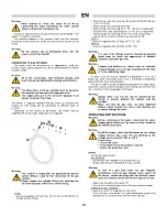
  Keep pressed the gas valve button (13) for 15 / 20 seconds until 

the  thermocouple  is  sufficiently  heated:  when  button  13  is 
released, the flame stays on. 

A MODELS (with or without room thermostat connected) 

• 

  Move the switch (9): 


• 

  to position        if room thermostat is not connected 

• 

  to position         if room thermostat is connected and set it to a 

temperature higher than room temperature 

• 

  Automatic starting cycle starts and light (8) flashes rapidly until 

the flame lights up. 

If the heater still does not function, see 

TROUBLESHOOTING” ЭШ 

identify the cause of the malfunction. 

 
STOP 

To stop operation turn 

ЭСО ЬаТЭМС (9) ЭШ ЩШЬТЭТШЧ “0” ТП ШЩОЫКЭТШЧ ТЬ 

manual, or, for A model, turn thermostat adjustment down: the flame 
goes out and the fan motor stops.


Lastly,  close  the  gas  supply  stopcock  and  turn  off  the  isolation 

switch. 


Warning 

For M model: wait at least 2 minutes before restarting 
the  heater,  to  allow  the  thermocouple  to  cool 
completely.


Warning 

If  the  heater  is  not  used  continuously,  stop  it  by  first 
closing the gas supply stopcock and then switch it off 
by  pressing  button  (9)  or  by  turning  down  the 
thermostat: 


this allows the gas in the gas tube to be fully used and 
avoids any future leak when removing the gas tube. 

 
For type A model, a post-ventilation mode can be selected to cool 

the combustion chamber for 30 seconds when the heater is stopped. 
To  select  this  function,  insert  the  PVC  connector  (in  the  electrical 
board) in the electronic control box (see WIRING DIAGRAM).


VENTILATION 

Type M models can be used as fans: simply disconnect gas tube 

from gas bottle and turn the switch (9) to position (I).


TRANSPORTING AND HANDLING 

The space heater can be lifted and moved by means of its handle. 


Warning 

Before moving the unit: 

• 


SЭop  ЭСО  СОКЭОЫ  КЬ  ТЧНТМКЭОН  ТЧ  ЭСО  “STOP” 

paragraph; 

• 

  Disconnect  the  power  supply  by  removing  the  plug 

from the power socket; 

• 

  Close  the  gas  stopcock  and  disconnect  the  gas 

hose; 

• 

  Wait until the heater cools. 


Warning


During  transportation  and/or  storage,  make  sure  the 
gas  valve  group  and  gas  connection  pipes  are  not 
knocked or damaged in any way. 


MAINTENANCE 

For  efficient  operation  of  the  heater,  clean  the  fan  motor,  suction 

grill,  combustion  chamber,  and  burner  at  regular  intervals.  Remove 
all debris. 

 
Warning


Before doing any maintenance: 

• 


SЭop  ЭСО  СОКЭОЫ  КЬ  ТЧНТМКЭОН  ТЧ  ЭСО  “STOP” 

paragraph; 

• 

  Disconnect  the  power  supply  by  removing  the  plug 

from the power socket; 

• 

  Close the gas supply stopcock; 

• 

  Wait until the heater cools. 


Warning 

Incorrect  cleaning  of  the  heater  can  cause  damage  to 
property and/or people. 


Summary of Contents for GP 30A

Page 1: ...allu Biemmedue GP 85 C http www vseinstrumenti ru klimat teplovye_pushki gazovye ballu biemmedue gp_85a_c http www vseinstrumenti ru klimat teplovye_pushki gazovye ballu biemmedue gp_85a_c tab Respons...

Page 2: ...1 51 GP 30A GP 45A GP 65A GP 85A Code 128...

Page 3: ...l A 7 ELETTRODO DI IONIZZAZIONE Modello A ELECTRODE D IONISATION M A IONISATIONSELEKTRODE Modell A IONISATION ELECTRODE A model ELECTRODO DE IONIZACION Modelo A IONISATIE ELEKTRODE Model A ELEKTRODA J...

Page 4: ...ve essere di almeno 2 m Attenzione No o o o p o materiali infiammabili Attenzione L o o o o o o o o pericoloso per il ristagno di gas propano e o butano Assicurarsi che Le istruzioni contenute nel pre...

Page 5: ...tenzione po o utilizzato il raccordo opportuno per il collegamento alla bombola o bidone di gas Avvitare sempre prima il raccordo alla bombola e solo o o p o dotato di un raccordo girevole MODO I rego...

Page 6: ...i modelli M attendere almeno 2 minuti per il completo raffreddamento della termocoppia prima di accend o o Attenzione S o o o o o o o opportuno ogni volta spegnere il generatore chiudendo prima il rub...

Page 7: ...C C siano eccessive L C M elettronico per modelli A ed il collegamento elettrico ed eventualmente sostituirlo C T C L ia non si scalda e la valvola gas termica si chiude modello M M DV R premuto il pu...

Page 8: ...8 LI L Attention To o o o o o ANOMALIES DE ONCTIONN M NT CAUS S T SOLUTIONS L o A p p o o pp o o 8 o o Attention L o o o 8 q p o q mod A p o l appareil fonctionne correctement clignotement rapide mac...

Page 9: ...2 L E eurs Attention L q o p o p o Visser toujours le raccord d abord sur la bouteille et o i d un raccord rotatif MODE I G5 AT BG CY DK DE EE LT LV MK MT RO TR NL raccord G5 G2 avec fixation de type...

Page 10: ...re pendant au moins 2 minutes pour permettre le refroidissement complet du thermocouple Attention S o o o q o o p pp l interrupteur 9 ou en agissant sur le thermostat C p o o p o p o o op po A A post...

Page 11: ...fonctionner MODELE A 8 A V V bit V I combustion V V C C pas excessif L C M A C T C L rmocouple ne chauffe pas et la soupape de gaz thermique se referme M M DV R pendant au moins 30 secondes C D T M M...

Page 12: ...ektronik Modelle A kann auf unterschiedliche Weise leuchten Ausgeschaltet o B Schnelles Blinken S aus Langsames Blinken Pausen oder Bereitschaftszustand in Erwartung der Anforderung des Heizbetriebs S...

Page 13: ...en von Gasdruckreglern geliefert werden Achtung Es liegt in der Verantwortung des Installateurs sicherzustellen dass das richtige Fi Anschluss der Gasflasche verwendet wird Stets zuerst das Fitting un...

Page 14: ...G F ermitteln STILLSETZUNG S G S 9 P 0 Modelle M M DV oder A zu schalten bzw der Raumluftthermostat M A Die Flamme erlischt dann und der Ventilatormotor schaltet sich aus D G Trennschalter auszuschalt...

Page 15: ...n Modellen A und den S auswechseln D P S efekt T D T T M M M DV D E T T 30 S halten D P T D T Thermoelement defekt Modell M M DV D T auswechseln D I Flamme nicht Modell A D F bzw auswechseln A K einwa...

Page 16: ...e of gas stagnation Make sure that The instructions in this manual are carefully followed The heater is not installed in an area where there is a high risk of fire or explosions No flammable materials...

Page 17: ...equested seal for NL to install on G5 pressure regulator for NL TYPE II pressure regulator with G7 fitting for FI IE GB TYPE III pressure regulator with G9 fitting for SE NO Warning The seal of the fi...

Page 18: ...ly used and avoids any future leak when removing the gas tube For type A model a post ventilation mode can be selected to cool the combustion chamber for 30 seconds when the heater is stopped To selec...

Page 19: ...t and replace it if necessary T and gas valve closes M M DV models R eration keeping thermal gas valve button pressed for at least 13 seconds C R F M M DV models C I ctrode does not detect a flame A m...

Page 20: ...stablecimiento 8 la luz roja fija desaparece A El pulsador 8 del q po o o o A p p o o p q o o regularmente p p o p o q o ciclo de arranque p p o o q p o d p p luz fija q o oq o RECOMENDACIONES GENERAL...

Page 21: ...rlos se los debe girar en sentido contrario al de las agujas del reloj A Las o o o q o p L p o p p p o 2 El generador de aire caliente se suministra con tubo de gas a y bombonas de diferente tipo S A...

Page 22: ...Para detener el funcionamiento del aparato se debe desplazar el 9 0 M M DV A A la llama se apaga y el motor del ventilador cesa de funcionar inmediatamente P desconectar el interruptor de seccionamie...

Page 23: ...os L C para los M A C A C o de ser necesario E M M DV R 30 C E T M M DV C E presencia de llama modelo A E iarlo o sustituirlo I funcionamiento irregular del quemador modelo A D S A T A modelo A C aso...

Page 24: ...RU 23 EN 1596 2008 G31 G30 G31 I 8 8 8 2 3 EN 1596 2008 100 3 100 3 25 2 250 2...

Page 25: ...RU 24 10 2 I G5 AT BG CY DK DE EE LT LV MK MT RO TR NL G5 G2 G2 BE CZ ES FR HR HU LU PL PT SI SK G5 G1 G1 IT GR G5 G7 G7 FI IE GB G5 G9 G9 SE NO G5 G5R G5R CH NL NL G5 NL II G7 FI IE GB III G9 SE NO...

Page 26: ...RU 25 9 0 9 8 9 0 9 30 PVC...

Page 27: ...RU 26 8...

Page 28: ...RU 27 RU 0001 11 B51 109599 74 2 II 109599 74 2 II 8 495 991 45 42 8 499 372 01 67 C IT AB51 B 02155 12 02 2013 12 02 2015 BIEMMEDUE S p A Via Industria 12 12062 Cherasco CN Italy...

Page 29: ...RU 28 Ballu Biemmedue Ballu Biemmedue 1 2 1 2 3 4 5 6 7 8 9 12 ________________ 201...

Page 30: ...______________________________________________________________________________ ______________________________________________________________________________ _________________________________________...

Page 31: ...nipperen het apparaat is in pauze of verwarmingsverzoek vast licht het apparaat is in de geblokkeerde toestand ALGEMENE AANBEVELINGEN De installatie de afstelling en het gebruik van de luchtverhitter...

Page 32: ...sen geleverd Afhankelijk van het land van bestemming kan de luchtverhitter met diverse soorten gasdrukregelaars worden geleverd Opgelet Het is de verantwoordelijkheid van de installateur om te control...

Page 33: ...erhitter opnieuw in te schakelen Opgelet Als de luchtverhitter niet voortdurend wordt gebruikt is het verstandig hem elke keer uit te schakelen door eerst de gastoevoerkraan te sluiten en vervolgens o...

Page 34: ...sche aansluiting en vervang deze eventueel C D C H thermische gasklep sluit model M M DV H thermische gasklep minstens 30 seconden ingedrukt C V D odel M M DV C eventueel D elektrode detecteert niet d...

Page 35: ...o o o AL C NIA O LN Insta M 2 m Uwaga N o po o o op Uwaga Stosowanie w suterenach lub w pomieszczeniach po po o p po o zastoju propanu i lub butanu U Instrukcje zam przestrzegane G 3 S P nagrzewnica m...

Page 36: ...wnica powietrza jest dostarczana razem z przewodem gazu gazu Uwaga I o o o p o po o o o o po p o o op o p o po o o o o TYP I G5 AT BG CY DK DE EE LT LV MK MT RO TR NL G5 G2 G2 BE CZ ES FR HR HU LU PL...

Page 37: ...zycji C 8 J NIEPRA ID O O CI D IA ANIA PR C N I RODKI ARADC E ZATRZYMANIE 9 0 M M DV A termostatu otoczenia tylko modele A N Uwaga W przypadku modeli M p po o po o 2 o o o op Uwaga J o po p p 9 termos...

Page 38: ...DEL M M DV wentylator nadal pracuje MODEL A 8 koloru czerwonego N S S gazu S powodu przegrzania komory spalania S zatkane S przewietrzane S S P S modelach M elektroniczny w modelach A oraz go S onowej...

Page 39: ...LLAMPE RESET BUTTON PULSADOR RESTABLECIMIENTO RESETKNOP MET CONTROLELAMPJE PRZYCISK RESETOWANIA AP APPARECCHIATURA DI CONTROLLO COFFRET DE SECURITE STEUEREINHEIT CONTROL BOX APARATO DE CONTROL CONTROL...

Page 40: ...ACI N D L T RMOPAR AFSTELSCHEMA THERMOKOPPEL SCHEMAT REGULACJI TERMOPARY A mm GP 30 33 GP 45 33 GP 65 50 5 GP 85 50 5 DESTINAZIONE EUROPEA D STINATION UROP NN BESTIMMUNGSGEBIET EUROPA EUROPE DESTINO E...

Page 41: ...1 538 3 153 Pressione gas Pression gaz Betriebs druck Gas pressure P Gasdruk C bar 0 4 1 5 0 4 1 5 Portata d aria D Nenn Lufleistung Air output Capacidad aire Luchtdebiet N m3 h 1 100 1 250 Temperatur...

Page 42: ...h 2 189 4 472 2 779 5 757 Pressione gas Pression gaz Betriebs druck Gas pressure P Gasdruk C bar 0 4 1 5 0 4 1 5 Portata d aria D Nenn Lufleistung Air output Capacidad aire Luchtdebiet N m3 h 1 950 2...

Page 43: ...ONTAGGIO KIT RUOTE NOTICE DE MONTAGE DU KIT DE ROUS ANLEITUNG R DI MONTA DES RAEDERSATZES WHEELS KIT ASSEMBLY INSTRUCTION INSTRUCCIONES DE MONTAJE DEL KIT RUEDAS MONTAGE INSTRUCTIE WIELENKIT INSTRUKCJ...

Page 44: ...E MANIGLIA NOTICE DE MONTAGE DU PIED DE LA POIGNEE ANL ITUN R DI MONTA D S USS S HANDGRIFFES FOOT HANDLE ASSEMBLY INSTRUCTION INSTRUCCIONES DE MONTAJE PIE MANILLA MONTAGE INSTRUCTIE VOETSTUK HANDGREEP...

Reviews: