background image

8

english

BAE PS-XA-3Y-24-250-609-I / BAE PS-XA-3Y-24-250-611-I

Power supply units

Product description

4.1 

Construction

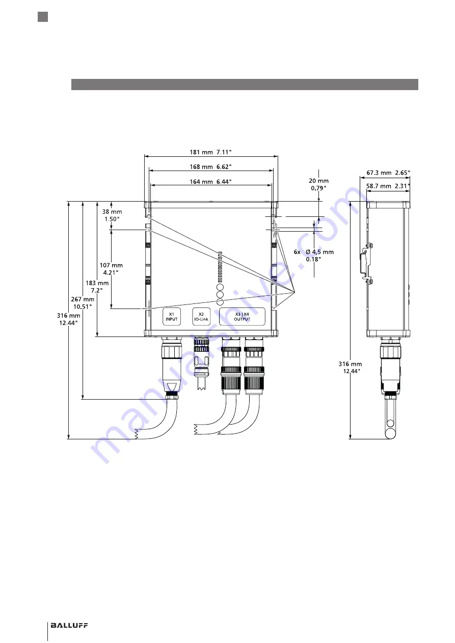
4.1.1  BAE PS-XA-3Y-24-250-609-I

Fig. 4-1: 

Mounting 

holes (6 ×)

Dimensions BAE PS-XA-3Y-24-250-609-I

Summary of Contents for BAE PS-XA-3Y-24-250-609-I

Page 1: ...BAE PS XA 3Y 24 250 609 I BAE PS XA 3Y 24 250 611 I deutsch Betriebsanleitung english User s Guide...

Page 2: ...www balluff com...

Page 3: ...BAE PS XA 3Y 24 250 609 I BAE PS XA 3Y 24 250 611 I Betriebsanleitung deutsch...

Page 4: ...www balluff com...

Page 5: ...609 I 8 4 1 2 BAE PS XA 3Y 24 250 611 I 9 4 2 Funktion 10 4 2 1 Eingang X1 10 4 2 2 IO Link Anschluss X2 10 4 2 3 DC Ausgang X3 X4 10 4 3 Bedien und Anzeigeelemente 11 4 3 1 Bedienelemente 11 4 3 2 S...

Page 6: ...eine Merkmale 19 8 2 Umgebungsbedingungen 19 8 3 Elektrische Merkmale 19 8 4 Elektrischer Anschluss 21 8 5 Ausgang Schnittstelle 21 8 6 Mechanische Merkmale 21 8 7 Zulassungen und Kennzeichnungen 21 9...

Page 7: ...k angezeigt Handlungsanweisung 1 Handlungsabfolgen werden nummeriert dargestellt 1 Handlungsanweisung 1 2 Handlungsanweisung 2 Zahlen ohne weitere Kennzeichnung sind Dezimalzahlen z B 23 Hexadezimale...

Page 8: ...n Insbesondere muss der Betreiber Ma nahmen treffen dass bei einem Defekt des Produkts keine Gefahren f r Personen und Sachen entstehen k nnen Das Produkt darf nicht ge ffnet umgebaut oder ver ndert w...

Page 9: ...1 Lieferumfang Netzger t Montageanleitung 3 2 Transport Produkt in Originalverpackung bis zum Verwendungs ort transportieren 3 3 Lagerbedingungen Produkt in Originalverpackung lagern Umgebungsbedingun...

Page 10: ...eutsch BAE PS XA 3Y 24 250 609 I BAE PS XA 3Y 24 250 611 I Netzger te 4 Produktbeschreibung 4 1 Aufbau 4 1 1 BAE PS XA 3Y 24 250 609 I Bild 4 1 Befestigungs l cher 6 Abmessungen BAE PS XA 3Y 24 250 60...

Page 11: ...com 9 deutsch BAE PS XA 3Y 24 250 609 I BAE PS XA 3Y 24 250 611 I Netzger te 4 1 2 BAE PS XA 3Y 24 250 611 I Bild 4 2 Befestigungs l cher 6 Abmessungen BAE PS XA 3Y 24 250 611 I 4 Produktbeschreibung...

Page 12: ...rennt ist Das negative Potential der Ausg nge ist im Ger t fest mit PE verbunden keinen Ausgang an PE Masse anschlie en Das Ger t ist f r die Versorgung aller Arten von Lasten einschlie lich kapazitiv...

Page 13: ...ED Signal Bedeutung Aus Die Gleichspannung liegt unter 90 der Sollwertspannung oder ein Ausgangskanal hat ausgel st oder das Netzteil ist nicht eingeschaltet Gr n statisch Die Gleichspannung liegt ber...

Page 14: ...r Ausgang wurde ausgel st Der Ausgangsstrom des Ausgangs hat ca 48A berschritten Gr nde f r einen Kurzschluss k nnen ein elektri scher Kurzschluss Lasten au erhalb der Spezifikation das Einstecken ein...

Page 15: ...nearly between 55 C and 70 C Operational temperature range 25 C to 70 C ATTENTION LIRE LE MANUEL BAE PS XA 3Y 24 250 609 I INSTALLATION MANUAL Power Supply 3 Phase 4x DC 24V 600W BAE012P BAE PS XA 3Y...

Page 16: ...hern befestigen Die empfohlene Schraubengr e ist M4 5 1 2 Montageausrichtung Standardorientierung IN IOL OUT Netzger t Bild 5 1 350 500 600 0 45 55 70 Ausgangsleistung W Umgebungstemperatur C Zul ssig...

Page 17: ...erhalb des Ger ts an Eingang X1 BAE PS 609 I BAE PS 611 I 3 1 4 2 7 8 Stecker M12 Stecker S codiert Bild 5 3 Pinbelegung Eingang X1 Draufsicht auf Stecker am Ger t Pin Signal 1 L1 2 L2 3 L3 4 PE Tab 5...

Page 18: ...n an Dies ist der Standardmodus der LED Leiste Die Ausgangsleistung wird in Prozent der unter 55 C verf gbaren Leistung angezeigt 500 W 100 Wenn die LED Leiste z B bis 50 eingeschaltet ist werden 250...

Page 19: ...zur cksetzen Taste OUT des Ausgangs 1 4 mindestens 1 s gedr ckt halten 6 7 2 Phasenbetrieb Es sind keine externen Schutzvorrichtungen zum Schutz vor Phasenausfall erforderlich Ein kontinuierlicher zw...

Page 20: ...ur ckzuf hren Senden Sie das Ger t zur Reparatur an Balluff zur ck 7 2 Reparatur Reparaturen am Produkt d rfen nur von Balluff durchge f hrt werden Sollte das Produkt defekt sein nehmen Sie Kontakt mi...

Page 21: ...l BAE PS 609 I 10 A BAE PS 611 I 12 A Eingangsspannung 380 480 V 15 3 Phasen Leistungsfaktor1 0 94 0 95 Einschaltstrom1 1 9 1 8 Apeak Effizienz1 95 8 95 6 Verluste1 22 23 W berbr ckungszeit1 24 24 ms...

Page 22: ...ramm Bild 8 4 Zeitverz gerung vor dem Abschalten bei berlast typisch s Ausgangsstrom typisch A Ausl sekurvendiagramm Eingangsstrom Bild 8 5 0 0 0 2 0 4 0 6 0 8 1 0 600 400 500 300 200 100 0 Eingangsst...

Page 23: ...611 I M12 Buchse 5 polig L codiert 8 5 Ausgang Schnittstelle IO Link IO Link Protokoll V1 1 Condition Monitoring Remote Parametrierung 8 6 Mechanische Merkmale Abmessungen ohne Stecker 181 183 59 mm...

Page 24: ...50 611 I Netzger te 956535_AA DE D23 nderungen vorbehalten 9 1 Blockdiagramm BAE PS XA 3Y 24 250 609 I Bild 9 1 Blockdiagramm BAE PS XA 3Y 24 250 609 I 9 2 Blockdiagramm BAE PS XA 3Y 24 250 611 I Bild...

Page 25: ...BAE PS XA 3Y 24 250 609 I BAE PS XA 3Y 24 250 611 I User s Guide english...

Page 26: ...www balluff com...

Page 27: ...9 I 8 4 1 2 BAE PS XA 3Y 24 250 611 I 9 4 2 Function 10 4 2 1 Input X1 10 4 2 2 IO Link connection X2 10 4 2 3 DC output X3 X4 10 4 3 Operating and display elements 11 4 3 1 Operating elements 11 4 3...

Page 28: ...19 8 1 General features 19 8 2 Ambient conditions 19 8 3 Electrical data 19 8 4 Electrical connection 21 8 5 Output Interface 21 8 6 Mechanical features 21 8 7 Approvals and designations 21 9 Appendix...

Page 29: ...al instructions are indicated by a preceding triangle Instruction 1 Action sequences are numbered consecutively 1 Instruction 1 2 Instruction 2 Numbers unless otherwise indicated are decimals e g 23 H...

Page 30: ...or must take steps to ensure that a defect in the product will not result in hazards to persons or equipment The product must not be opened modified or changed If defects and unresolvable faults occur...

Page 31: ...s 3 1 Scope of delivery Power supply unit Installation guide 3 2 Transport Transport product to location of use in original packaging 3 3 Storage conditions Store product in original packaging Observe...

Page 32: ...sh BAE PS XA 3Y 24 250 609 I BAE PS XA 3Y 24 250 611 I Power supply units 4 Product description 4 1 Construction 4 1 1 BAE PS XA 3Y 24 250 609 I Fig 4 1 Mounting holes 6 Dimensions BAE PS XA 3Y 24 250...

Page 33: ...com 9 english BAE PS XA 3Y 24 250 609 I BAE PS XA 3Y 24 250 611 I Power supply units 4 1 2 BAE PS XA 3Y 24 250 611 I Fig 4 2 Mounting holes 6 Dimensions BAE PS XA 3Y 24 250 611 I 4 Product descriptio...

Page 34: ...ltage PELV ES1 which is galvanically isolated from the input voltage The negative potential of the outputs is permanently connected to PE in the device do not connect an output to PE ground The device...

Page 35: ...time see Fig 4 5 Fig 4 5 Status LED Signal Meaning Off The DC voltage is below 90 of the setpoint voltage or an output channel has tripped or the power supply unit is not switched on Green static The...

Page 36: ...t circuit The output was triggered The output current of the output has exceeded approx 48A Reasons for a short circuit can be an electrical short loads outside the specification plugging in a large c...

Page 37: ...W at 70 C Derate linearly between 55 C and 70 C Operational temperature range 25 C to 70 C ATTENTION LIRE LE MANUEL BAE PS XA 3Y 24 250 609 I INSTALLATION MANUAL Power Supply 3 Phase 4x DC 24V 600W BA...

Page 38: ...ed screw size is M4 5 1 2 Mounting orientation Standard orientation IN IOL OUT Power supply unit Fig 5 1 350 500 600 0 45 55 70 Output power W Ambient temperature C Permissible output power standard o...

Page 39: ...Input X1 BAE PS 609 I BAE PS 611 I 3 1 4 2 7 8 connector M12 connector S coded Fig 5 3 Pin assignment input X1 top view of connector on device Pin Signal 1 L1 2 L2 3 L3 4 PE Tab 5 1 Pin assignment inp...

Page 40: ...of the LED bar The output power is displayed as a percentage of the power available below 55 C 500 W 100 For example if the LED bar is switched on to 50 250 W will be consumed If the LED bar rises ab...

Page 41: ...ff Reset output Hold down the OUT key of output 1 4 for at least 1 s 6 7 2 phase operation No external protection devices are required to protect against phase failure Continuous two phase operation i...

Page 42: ...nternal fuse is due to an internal defect Return the device to Balluff for repair 7 2 Repair Repairs to the product may only be performed by Balluff If the product is defective contact our Service Cen...

Page 43: ...ntinuous output current adjustable per channel BAE PS 609 I 10 A BAE PS 611 I 12 A Input voltage 380 480 V 15 3 phases Power factor1 0 94 0 95 Inrush current1 1 9 1 8 Apeak Efficiency1 95 8 95 6 Losse...

Page 44: ...Trip curve diagram Fig 8 4 Time delay before switch off on overload typical s Output current typical A Trip curve diagram Input current Fig 8 5 0 0 0 2 0 4 0 6 0 8 1 0 600 400 500 300 200 100 0 Input...

Page 45: ...socket 5 pin BAE PS 611 I M12 socket 5 pin L coded 8 5 Output Interface IO Link IO Link protocol V1 1 condition monitoring remote parameterization 8 6 Mechanical features Dimensions without connector...

Page 46: ...1 I Power supply units 956535_AA EN D23 Subject to modification 9 1 Block diagram BAE PS XA 3Y 24 250 609 I Fig 9 1 Block diagram BAE PS XA 3Y 24 250 609 I 9 2 Block diagram BAE PS XA 3Y 24 250 611 I...

Page 47: ......

Page 48: ...uidling A Yunding International Commercial Plaza 200125 Pudong Shanghai China Headquarters und Technical Service Hub Region EMEA Balluff GmbH Schurwaldstrasse 9 73765 Neuhausen a d F Germany Technical...

Reviews: