www.balluff.com
29
english
Switchpoint Mode
The AdSS profile only supports one switching
point (setpoint). Accordingly, only the Single Point
Mode is available in this profile.
The hysteresis can be set and adjusted in the
LSSC profile. The interpretation of the hysteresis
can be implemented in both profiles specific to the
product. e.g. as a percentage value as opposed to
generic implementation as a fixed value.
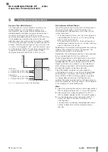
Single Point Mode
In Single Point Mode, only one switching point (setpoint) is
defined.
Switching behavior:
– Measurement value ≥ switching point: output active
– Measurement value ≤ switching point minus a defined
hysteresis: output inactive
Fig. 5-4:
High
SP1
SP1-Hys
Low
Measured value
Switch output
Single point mode
Two-Point Mode
In Two-Point Mode, two switching points (setpoints) are
defined.
Switching behavior:
– Measurement value ≥ switching point 1: output active
– Measurement value ≤ switching point 2: output inactive
Fig. 5-5:
High
SP1
SP2
Low
Measured value
Switch output
Two-Point Mode
5
Primary Device Functions (continued)
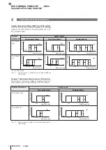
Window Mode
In Window Mode, two switching points (setpoints) are
defined.
Switching behavior:
– If the output is inactive and the measurement value is
greater than or equal to switching point 2 + 50% of the
set hysteresis or the measurement value is less than or
equal to switching point 1 – 50% of the set hysteresis,
the output switches to active.
– If the output is active and the measurement value is
less than or equal to switching point 2 – 50% of the set
hysteresis or the measurement value is greater than or
equal to switching point 1 + 50% of the set hysteresis,
the output switches to inactive.
Fig. 5-6:
High
SP1
SP2
Hyst.
Hyst.
Low
Measured
value
Switch output
Window Mode
Teach procedure
The following conditions must be met for successful
teach-in and for the direct setting of a setpoint:
– The setpoint that is to be taught must be in the validity
range of the measurement value signal.
Additionally in Two-Point and Window Mode:
– Setpoint 1 must be greater than setpoint 2.
– The distance between the setpoints must be greater
than or equal to the minimum hysteresis.
Due to the requirements listed above, it may be
necessary to vary the order of the setpoints for a
successful teach-in.
An active teach process is indicated by the
Teach-In
indicator (green-yellow LED changes slowly).
If the
Teach-In No Object
indicator flashes (green LED
flashing quickly), the current measured value is outside the
validity range (IO-Link method) or manual teach-in was not
possible.
Manual teach-in procedure
The manual teach-in is a Single Value Teach of setpoint 1
in single point switching mode. With this process, only
SSC 1 can be taught. The teach-in process is started with
the rising edge on pin 2.
An active teach-in process is indicated by the
Teach-In
indicator (green-yellow LED changes slowly).
If the green LED lights up continuously (
Ready
or
Communication
indicator), the teach-in process has been
successfully completed.
BCS Q40BBAA-PIM20C-EP _ _ _ -GS04
Capacitive Proximity Switches
Summary of Contents for BCS Q40BBAA-PIM20C-EP-GS04 Series
Page 1: ...BCS Q40BBAA PIM20C EP___ GS04 deutsch Konfigurationsanleitung english Configuration Guide...
Page 2: ...www balluff com...
Page 3: ...BCS Q40BBAA PIM20C EP___ GS04 Konfigurationsanleitung deutsch...
Page 4: ...www balluff com...
Page 87: ...BCS Q40BBAA PIM20C EP___ GS04 Configuration Guide english...
Page 88: ...www balluff com...
Page 171: ......


