Balluff Inductive Coupler
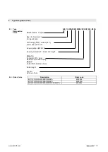
Base BIC 1I3-P2A50-M30MI3-SM4ACA und
Remote BIC 2I3-P2A50-M30MI3-SM4ACA
Remote BIC 2I3-P2A50-M30MI3-BPX0C-002-M4CA
www.balluff.com
4
3
Construction and Function
3.1.
Construction
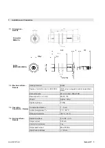
The system is designed for applications with up to 8 sensors. It consists of the following two
components:
•
Base (transmitter)
•
Remote (receiver)
The components are enclosed in a brass housing protected acc. to IP 67
Sensors
For the standard version of electronic sensors, the following are to be observed:
•
Make certain that the total power consumption of the sensor is not greater than that of
the base.
•
Only use sensors with a voltage of 24 V DC
Mechanical switches
For the standard version of mechanical switches, the following are to be observed:
•
Use switches for small load currents
•
Use switches with a residual current I <0.1 mA in the open switching state
•
The total resistance of the circuit should be less than 1 kOhm
3.2.
Function
This set transfers power from the base to the remote via an air bridge; the base then
receives data back from the remote. The base and remote must match one another with
respect to size.
The sensors are wired to the remote. The remote is only inductively coupled to the base,
however. The base transmits the energy for the sensors to the remote. The signal from the
sensors is transmitted to the base by the remote.
The energy available for the sensors is dependent on the distance and on the offset
between base and remote and is, therefore, limited. For this reason, the total current
consumption of the connected sensors must not exceed the maximum power output of the
remote.
3.3.
Features,
Advantages
•
The cable length between the remote and consumers is limited depending on the cable
resistance.
•
LED indicator on the remote and base for operational readiness and operating voltage
•
Angle offset is possible between base and remote
•
Simple wiring of e.g. rotary tables, replaceable punch heads etc.
•
M12 plug connection on the systems
•
Control of capacitive loads
•
More power in the same structural shape
•
Large operating voltage range
3.4.
Display
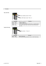
If the supply voltage is applied correctly, the green LEDs on the base and remote illuminate.
If the green LEDs on the base only flash, the supply voltage is too low.
As soon as the yellow LED on the base illuminates, data transmission is also secured.
As soon as the remote moves out of the secured working range, its green LEDs begin to
flash and the yellow LED on the base switches off.


