Balluff Inductive Coupler
Base BIC 1I3-P2A50-M30MI3-SM4ACA und
Remote BIC 2I3-P2A50-M30MI3-SM4ACA
Remote BIC 2I3-P2A50-M30MI3-BPX0C-002-M4CA
www.balluff.com
6
5
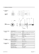
Installation and Connection
5.1.
Mutual
Interference
Attention!
Improper mounting may affect the function of the system and lead to damage.
The spacings specified for installation must be adhered to.
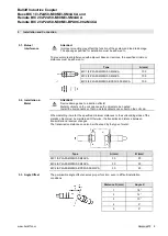
To prevent mutual interference with adjacent bases or remotes, the specified minimum
distances must be adhered to:
Type
A (mm)
BIC 1I3-P2A50-M30MI3-SM4ACA
100
BIC 2I3-P2A50-M30MI3-SM4ACA
100
BIC 2I3-P2A50-M30MI3-BPX0C-002-M4CA
100
5.2.
Installation in
Metal
Attention!
Device damage due to induction effects!
Metallic objects on the coil cap cause the objects to be heated.
Install the components so that no metallic objects can collect on the coil cap.
When installing in metal, the specified minimum distances to the surrounding sides of the
metallic object must be maintained. Otherwise, the transmission distance between
transmitter and receiver changes.
The transmission distance can also be influenced by the type of metal.
Type
A (mm)
B (mm)
BIC 1I3-P2A50-M30MI3-SM4ACA
30
20
BIC 2I3-P2A50-M30MI3-SM4ACA
30
20
BIC 2I3-P2A50-M30MI3-BPX0C-002-M4CA
30
20
5.3.
Angle Offset
The permissible angle offset ensures proper function, even in difficult installation
conditions:
Distance D (mm)
Angle X
1
18°
2
12°
3
10°
4
5°
5
0°

