
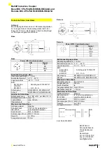
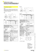
Balluff Inductive Coupler
Base BIC 1P0-P2A50-M30MI3-SM4A4A und
Remote BIC 2P0-P2A50-M30MI3-SM4A5A
3
Safety Notes
Proper Use
The device is designed to replace a plug connection in
order to ensure contact-free data transmission.
Before commissioning, carefully read the
operating manual!
These sensors must not be used in
applications in which the safety of persons is
dependent on the function of the device (not a
safety component acc. to EU machinery
directive).
Caution!
Risk of burning on hot surfaces!
The active surface heats up even under
normal operating conditions.
Keep away hands and objects from the active
surface.
Avoid contact of metal objects on the active
surface. Fire hazard!
Authorized Personnel
Installation and commissioning may only be performed
by trained specialist personnel.
Improper Use
In the event of damage cause by unauthorized tampering
or improper use, warranty and liability claims against the
manufacturer are rendered void.
Obligations of the Operating Company
The device corresponds to EMC Class A and can cause
radio interference. The operating company must take
appropriate precautions.
The operating company must ensure that the locally
applicable safety regulations are observed.
Malfunctions
In the event of defects and device malfunctions that
cannot be rectified, the device must be taken out of
operation and protected against unauthorized use.
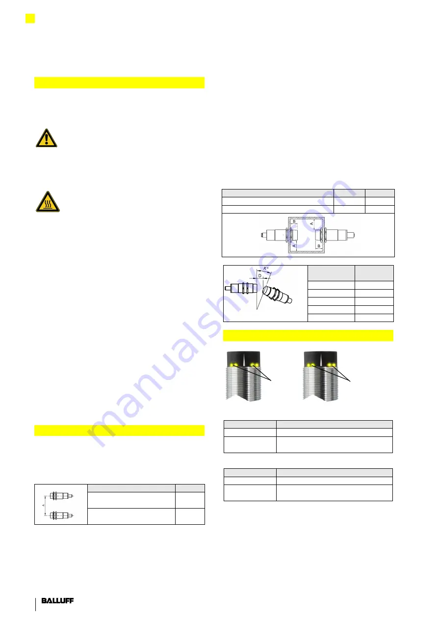
Installation
Mutual Interference
To prevent mutual interference with adjacent bases or
remotes, the specified minimum distances must be
adhered to:
Type
A (mm)
BIC 1P0-P2A50-M30MI3-
SM4A4A
100
BIC 2P0-P2A50-M30MI3-
SM4A5A
100
Installation in Metal
When installing in metal, the specified minimum
distances to the surrounding sides of the metallic object
must be maintained. Otherwise, the transmission distance
between transmitter and receiver changes. The
transmission distance can also be influenced by the type
of metal.
Note!
Device damage due to induction effects
Metallic objects on the coil cap cause the objects to be
heated.
Install the components so that no metallic objects can
collect on the coil cap.
Type
A (mm) B (mm)
BIC 1P0-P2A50-M30MI3-SM4A4A
30
20
BIC 2P0-P2A50-M30MI3-SM4A5A
30
20
Distance D
in mm
Angle X
in °
1
18°
2
12°
3
10°
4
5°
5
0°
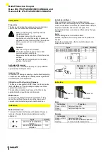
Indicators
Base
Remote
Base
Indicators
Function
Green
– static
Supply voltage OK
Green
–
flashing
Supply voltage too low
Remote
Indicators
Function
Green
– static
Supply voltage OK
Green
–
flashing
No connection between base and
remote, no data transmission
Power on
Power on


