13
deutsch
13
E
Function Description
Communication with the processor
Communication between the host system and the processor takes place using a fixed proto-
col sequence. Data integrity from the control to the processor and vice-versa is indicated by a
control bit. This bit is used to implement a handshake between the control and the processor.
Following is a simplified representation of the sequence of a job sent from the control to the
processor:
1. The control sends a command designator to the processor together with the associated
command parameters and sets a bit (AV bit). This bit indicates to the processor that the
transmitted data are valid and that the job is now beginning.
2. The processor takes the job and sets a bit (AA bit), which indicates this to the control.
3. If an additional exchange of data between the control and the processor is required to
carry out the job, each uses a bit (TI bit and TO bit) to indicate that the control / processor
is now ready for additional data exchange or has accepted the received data.
4. Once the processor has carried out the job correctly, it sets a bit (AE bit).
5. Once the control has accepted all the important data, it indicates this to the processor by
resetting the bit that was set at the beginning (AV bit).
6. The processor now in turn sets all the control bits that were set during the sequence
(AA bit, AE bit) and is ready for the next job.
Basic Procedure
C60_1-023_819395_0508_en.p65
14
14
E
Function Description
In- and Output Buffer on I
NTER
B
US
Input and Output
buffers
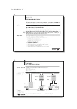
To transmit the control bit, commands and data between the BIS C-60_1 processor and the
host system, the latter must provide two fields. These two fields are:
–
the output buffer
for the control bit (bit header) and controller commands sent
to
the BIS identification
system,
for the data to be written, and
for configuring the BIS C-60_1 processor
–
the input buffer
for the control bit (bit header) of the BIS C-60_1 processor,
for the data to be read,
for the ID’s and error codes coming
from
the BIS identification system, and
for reading out the configuration data.
The total buffer size of the BIS C-60_1 is 16 bytes for the input buffer and 16 bytes for the
output buffer. This total buffer size is divided into 2 sectors:
Buffer sector 1 for Read/Write Head 1: 8 bytes input buffer, 8 bytes output buffer
Buffer sector 2 for Read/Write Head 2: 8 bytes input buffer, 8 bytes output buffer
Please note the
basic procedure on
13 and 28...35
and the examples on
pages
36...55.


