63
deutsch
63
E
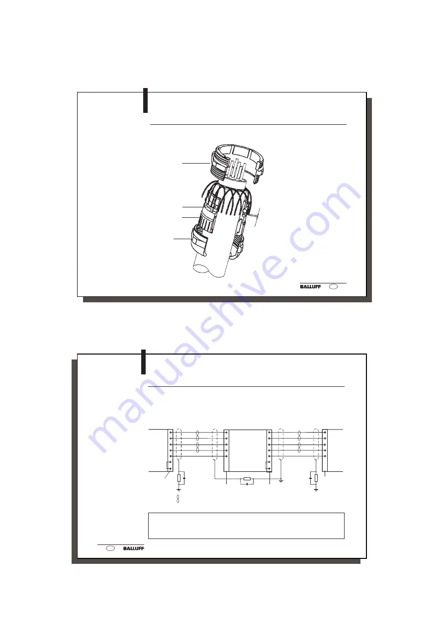
Mounting the PG
Connection on the
processor
BIS C-6001
BIS C-6001
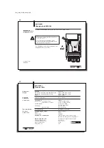
Mounting the PG Connection
After connecting the (field) bus leads to the terminal block, make sure that the shield has
proper connection to the PG housing.
Screw socket
Inside O-ring
Cable clamp
Screw the
swivel nut
with a torque
of 4.17 Nm
ca. 3 - 4 mm
C60_1-023_819395_0508_en.p65
64
64
E
10
11
8
9
12
6
7
10
11
8
9
12
6
7
1
2
3
4
5
/DI2
DI2
/DO2
DO2
GND
/RBST
RBST
1
2
3
4
5
/DI1
DI1
/DO1
DO1
GND1
/DI2
DI2
/DO2
DO2
GND
/RBST
RBST
/DI1
DI1
/DO1
DO1
GND1
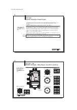
Remote bus cable
and interfaces for
I
NTER
B
US
To insert the BIS C-6001 processors into the serial I
NTER
B
US
, the terminal strip provides
terminals 1...5 for the input interface and terminals 8...12 for the output interface of the
I
NTER
B
US
. The following drawing shows the wiring when the BIS C-6001 processors need to
be connected together.
1
) Leave the jumper in the BIS C-6001 if an additional station is to follow.
Remove it if no additional station follows.
2
) The differential signals DO and /DO as well as DI and /DI must be twisted-pair.
Recommended cable: LiYCY 3x2x0.25 mm
2
(AWG 24); maximum cable capacitance: 120 pF/m
twisted-pair
2)
Input
terminal
block
BIS C-6001
Interface Information / Wiring Diagrams
Output
terminal
block
1)
2)
2)
1)
2)
2)
Bus station BIS C-6001
Bus station
BIS C-6001
Bus station
BIS C-6001
Output
terminal
block
Input
terminal
block


