65
deutsch
65
E
7
2
6
1
3
5
9
7
2
6
1
3
10
11
8
9
12
6
7
1
2
3
4
5
/DI2
DI2
/DO2
DO2
GND
/DI1
DI1
/DO1
DO1
GND1
/DI2
DI2
/DO2
DO2
GND
/RBST
RBST
/DI1
DI1
/DO1
DO1
GND1
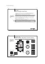
Remote bus cable
and interfaces for
I
NTER
B
US
(continued)
To insert the BIS C-6001 processors into the serial I
NTER
B
US
, the terminal strip provides
terminals 1...5 for the input interface and terminals 8...12 for the output interface of the
I
NTER
B
US
. The following drawing shows the wiring when the BIS C-6001 interface needs to
be connected using a 9-pin terminal (e.g. to a BIS C-6021).
1
) Connect the jumper in the connector if another station is to follow.
Remove it if no additional station follows.
2
) The jumper remains in the BIS C-601 if an another station is to follow.
Remove it if no additional station follows.
3
) The differential signals DO and /DO as well as DI and /DI must be twisted-pair.
Recommended cable: LiYCY 3x2x0.25 mm
2
(AWG 24); maximum cable capacitance: 120 pF/m
Shield connected
to connector
housing.
twisted pair
2)
Input
terminal
block
9-pin
MIN D
female,
output
9-poliger
MIN D-
Stecker,
Eingang
BIS C-6001
Interface Information / Wiring Diagrams
Shield con-
nected to
connector
housing.
Output
terminal
block
1)
3)
3)
2)
3)
3)
Bus station BIS C-6001
Bus station
Bus station
C60_1-023_819395_0508_en.p65
66
66
E
Wiring diagram for
BIS C-6001
processor with
integrated
read/write head
Power supply
and digital input
I
NTER
B
US
Input
I
NTER
B
US
Output
Terminal
block
BIS C-6001
Interface Information / Wiring Diagrams
Terminal block
assignments
Terminal location and
designation
UL
CC
BA
RD
5
4
3
2
1
GND DO1 /DO1
DI1
/DI1
I
NTER
B
US
Input
12
11
10
9
8
7
6
GND
DI2
/DI2
DO2 /DO2
RBST /RBST
I
NTER
B
US
Output
19
18
17
16
15
14
13
+ VS - VS
TxD
RxD GND
+IN
-IN
Power
RS 232
Digital Input
When connecting the bus lines, be sure that the shield
makes a good connection with the PG housing. Please
note the installation instructions on 63.


