67
deutsch
67
E
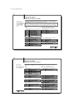
Connection for Read/Write Head 1
Connection for Read/Write Head 2
BIS C-6001
Interface Information / Wiring Diagrams
Wiring diagram for
BIS C-6001
processor with
BIS C-650 adapter
I
NTER
B
US
Output
I
NTER
B
US
Input
Terminal location and
designation
Terminal
block
Power supply and digital input
UL
CC
BA
RD
Terminal block
assignments
5
4
3
2
1
GND DO1 /DO1
DI1
/DI1
I
NTER
B
US
Input
12
11
10
9
8
7
6
GND
DI2
/DI2
DO2 /DO2
RBST /RBST
I
NTER
B
US
Output
19
18
17
16
15
14
13
+ VS - VS
TxD
RxD GND
+IN
-IN
Power
RS 232
Digital Input
When connecting the bus lines, be sure that the shield
makes a good connection with the PG housing. Please
note the installation instructions on 63.
C60_1-023_819395_0508_en.p65
68
68
E
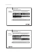
Connection for read/write head, 8-pin
BIS C-6001
Interface Information / Wiring Diagrams
Wiring plan for
BIS C-6001 using
BIS C-670 adapter
I
NTER
B
US
Output
I
NTER
B
US
Input
Connection location
and name
Terminal
block
Supply voltage and digital input
UL
CC
BA
RD
Terminal block
assignments
5
4
3
2
1
GND DO1 /DO1
DI1
/DI1
I
NTER
B
US
Input
12
11
10
9
8
7
6
GND
DI2
/DI2
DO2 /DO2
RBST /RBST
I
NTER
B
US
Output
19
18
17
16
15
14
13
+ VS - VS
TxD
RxD GND
+IN
-IN
Power
RS 232
Digital Input
When connecting the bus lines, be sure that
the shield makes a good connection with the
PG housing. Please note the installation
instructions on 63.


