BIS V-6108 PROFINET
Processor Unit
12
english
Note
Make the ground connection either directly or using an RC combination to ground.
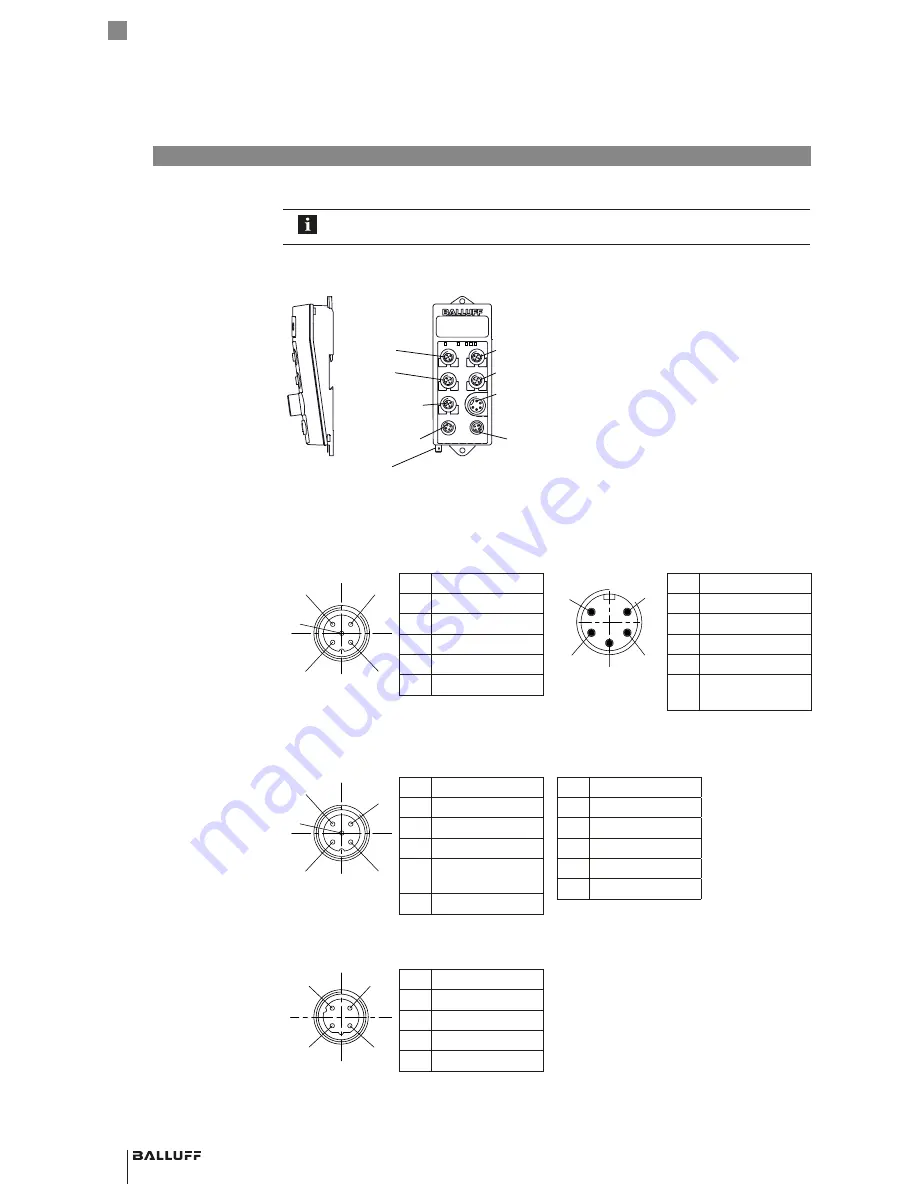
Connections
H 1
Port 1
Power
Port 2
H 2
H 4
H 3
Service /
IO-Link
FE
H1…H4
Read/Write Heads
Service/IO-Link
USB function
Service/IO-Link
(master function)
Port 1
PROFINET IO port 1
Port 2
PROFINET IO port 2
FE
Functional ground
Figure 4: Electrical Connections
H1…H4
M12 female, 5-pin, A-coded
Power
7/8" male, 5-pin
2
5
1
5
3
4
2
3
4
1
A
0V
B
H1...H4
VP
N.C.
PIN
Function
1
+24 V DC
2
A
3
0 V
4
B
5
n.c.
3
4
2
3
1
4
5
5
2
1
VP(Aktor)
VP(Sensor) BUS
FE
0V
0V
POWER
PIN
Function
1
0 V
2
0 V
3
FE
4
+24 V DC
5
Reserved, not
connected
IO-Link / Service
M12 female, 5-pin, A-coded
2
5
1
5
3
4
2
3
4
1
USB Tx
0V
Q/C (IO/Link)
IO-Link-Master
VP
USB Rx
IO-Link
PIN
Function
1
VP (+24 V DC)
2
n. c.
3
0 V
4
Q/C (IO-Link) or
digital input
5
n. c.
Service
PIN
Function
1
n. c.
2
USB–
3
0 V
4
n. c.
5
USB+
PROFINET IO port 1/2
M12 female, 4-pin, D-coded
4
1
3
2
PIN
Function
1
+Tx
2
+Rx
3
–Tx
4
–Rx
4.3 Electrical
Connections
4
Installation


