www.balluff.com
2
english
BMF 203K-H- _ _ -C-A _ -… / BMF 235K-H- _ _ -C-A _ -…
Magnetic Field Sensors
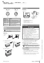
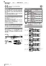
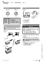
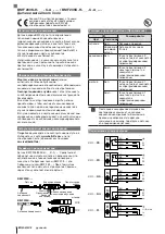
Electrical connection (continued)
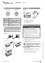
BMF…-S75
BMF…-S4
2
1
4
3
Class A
M 8
2
1
4
3
Class A
M 12-4
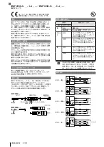
Pin / wire color
Signal
Pin 1/brown
+24V (operating voltage UB+)
Pin 2/white
OUT2 (Switching output S2)
Pin 3/blue
GND (operating voltage UB–,
reference potential)
Pin 4/black
OUT1 (Switching output S1) or
C/Q for IO-Link
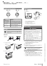
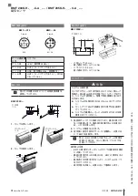
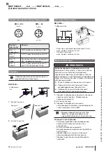
Installation
For determining the installation position see
user’s guide.
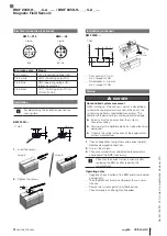
BMF 203K-…
C-slot
3
2.2
R1.8
4
3.8...4.2
3.0...3.2
1.
Insert the sensor.
Variant A
Variant B
2.
Tighten the sensor.
0.9
max. 0.07 Nm
Installation (continued)
BMF 235K-…
T-slot
0.9
max. 0.07 Nm
2.0
max. 0.4 Nm
5.0…5.4
> 3.5…> 6.0
< 4.0
– Allen wrench, 2.0 mm:
max. torque 0.4 Nm
– Screwdriver, 4×0.8 mm:
max. torque 0.4 Nm
Startup
DANGER
Uncontrolled system movement
When starting up, if the sensor is part of a closed loop
system whose parameters have not yet been set, the
system may perform uncontrolled movements. This
could result in personal injury and equipment damage.
►
Persons must keep away from the system’s
hazardous zones.
►
Startup must be performed only by trained technical
personnel.
►
Observe the safety instructions of the equipment or
system manufacturer.
1.
Check connections for tightness and correct polarity.
Replace damaged connections.
2.
Turn on the system.
3.
Check measured values and adjustable parameters
and readjust the BMF if necessary.
Check for the correct values, especially after
replacing the BMF or after repair by the
manufacturer.
Operating notes
– Regularly check function of the BMF and all associated
components.
– Take the BMF out of service whenever there is a mal-
function.
– Secure the system against unauthorized use.
– Check fasteners and re-tighten if needed.
No. 944153 EN · A20; subject to modification. Replaces K19.


