background image

www.balluff.com

7

日本語

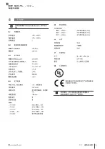
4.1 

機能

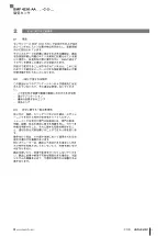
この磁気センサは、C スロット付きの空圧式シリンダお

よびグリッパで使用するよう設計されており、ピストン

に内蔵されているマグネットの磁場をアクチュエータの

壁を通して検出します。

4.2 

表示エレメント

LED

作動ステータス

ステータス

ON

スイッチポイントがアクティ

ブ。

OFF

スイッチポイントが非アクティ

ブ。

表 4-1: 

LED 表示

製品の説明

4.3 

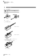
ケーブルプリント

図 4-2: 

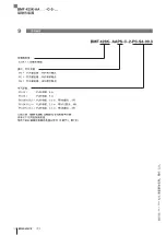
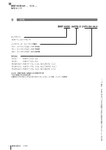
注文コード

タイプ

ケーブルプリント(例)

図 4-1: 

 ≤ 49 

 M12x1 

 ≤

 15 

 ≤ 49 

 M12x1 

 ≤

 15 

 M8x1 

 ≤

 11 

 ≤ 36.5 

Ø 

3.6 

 5 

 24 

Ø 

 M2 

1)

LED

 2.9 

 L 

≤ 39 

 ≤

 10 

 M8x1 

 L 

 L 

 L 

 L 

…-P0-S49-00,3

…-P0-02/05

(長さ = 0.3 m)

(長さ = 2/5 m)

(長さ = 0.3 m)

(長さ = 0.3 m)

(長さ = 0.3 m)

…-P0-S4-00,3

…-SA95-P0-S4-00,3

…SA95-P0-S75-00,3

寸法、構造、機能

BMF 423K-AA _ _ -C-2-…

磁気センサ

Summary of Contents for BMF 423K-AA C-2 Series

Page 1: ...BMF 423K AA_ _ C 2 deutsch Betriebsanleitung english User s Guide fran ais Notice d utilisation italiano Manuale d uso espa ol Manual de instrucciones portugu s Manual de Instru es...

Page 2: ...www balluff com...

Page 3: ...BMF 423K AA _ _ C 2 Betriebsanleitung deutsch...

Page 4: ...www balluff com...

Page 5: ...4 1 Funktion 7 4 2 Anzeigeelemente 7 4 3 Kabelbedruckung 7 5 Einbau und Anschluss 8 5 1 Sensor montieren 8 5 2 Kolbenposition mit einem Stabmagnet bestimmen 9 5 3 Elektrischer Anschluss 10 6 Inbetrie...

Page 6: ...nden Dokumenten Datenblatt Konformit tserkl rung Entsorgung 1 3 Verwendete Symbole und Konventionen Einzelne Handlungsanweisungen werden durch ein vorangestelltes Dreieck angezeigt Handlungsanweisung...

Page 7: ...gesetzt werden in sicherheitsgerichteten Anwendungen in denen die Personensicherheit von der Ger tefunktion abh ngt in explosionsgef hrdeten Bereichen im Lebensmittelbereich 2 3 Allgemeine Sicherheits...

Page 8: ...nes Zubeh r finden Sie unter www balluff com auf der Produktseite 3 2 Transport Produkt in Originalverpackung bis zum Verwendungs ort transportieren 3 3 Lagerbedingungen Produkt in Originalverpackung...

Page 9: ...szustand Farbe Zustand Gelb On Schaltpunkt ist aktiv Off Schaltpunkt ist inaktiv Tab 4 1 LED Anzeige 4 Produktbeschreibung 4 3 Kabelbedruckung Bild 4 2 Bestellcode Typ Kabelbedruckung Beispiel Bild 4...

Page 10: ...C Nut Bild 5 1 C Nut 3 6 3 3 8 4 2 3 3 2 4 2 2 1 Sensor einsetzen Variante A Variante B Bild 5 2 Montage BMF 203K in zwei Varianten 2 Sensor festziehen Schl ssel 0 9 Anzugsdrehmoment 0 07 Nm Bild 5 3...

Page 11: ...tabmagnet aufbringen 2 Zylinderstange komplett ausziehen Der Magnet bewegt sich mit Bild 5 5 Zylinderstange ausziehen 3 Position des Magneten markieren Mitte des Magneten Bild 5 6 Magnetposition marki...

Page 12: ...Braun UB 24 V Pin 2 Wei nicht belegt1 Pin 3 Blau UB GND Bezugspotenzial Pin 4 Schwarz Sensorausgang 1 1 bei BMF SA95 Sensorausgang 2 Tab 5 1 Pinbelegung Der Sensor verf gt ber einen berlastschutz Nach...

Page 13: ...ten 1 Anschl sse auf festen Sitz und richtige Polung pr fen Besch digte Anschl sse tauschen 2 System einschalten 3 Messwerte und einstellbare Parameter pr fen und ggf den Sensor neu einstellen Dabei E...

Page 14: ...tsch 7 1 Entsorgung Befolgen Sie die nationalen Vorschriften zur Entsor gung Weitere Informationen finden Sie unter www balluff com auf der Produktseite 7 Entsorgung BMF 423K AA _ _ C 2 Magnetfeld Sen...

Page 15: ...ypenschl ssel auf Seite 14 Kabeldurchmesser D 2 4 mm Kurzschlusschutz ja Verpolungssicher ja Verbindung P0 S49 M8x1 Stecker 3 polig P0 S4 M12x1 Stecker 3 polig P0 S75 M 8x1 Stecker 4 polig SA95 _ _ S4...

Page 16: ...bel 2 m P0 05 PUR Kabel 5 m P0 S49 00 3 PUR Kabel 0 3 m mit M8 Stecker 3 polig P0 S4 00 3 PUR Kabel 0 3 m mit M12 Stecker 4 polig P0 S75 00 3 PUR Kabel 0 3 m mit M8 Stecker 4 polig Bestellbeispiel BMF...

Page 17: ...BMF 423K AA _ _ C 2 User s Guide english...

Page 18: ...www balluff com...

Page 19: ...n 7 4 2 Display elements 7 4 3 Cable imprint 7 5 Installation and connection 8 5 1 Mounting the sensor 8 5 2 Determining the piston position with a rod magnet 9 5 3 Electrical connection 10 6 Startup...

Page 20: ...duct page e g in the following documents Data sheet Declaration of Conformity Disposal 1 3 Symbols and conventions Individual action instructions are indicated by a preceding triangle Instruction 1 Ac...

Page 21: ...not be used there In safety oriented applications in which personal safety depends on the device function In explosive atmospheres In food applications 2 3 General safety notes Activities such as ins...

Page 22: ...parately Recommended accessories can be found at www balluff com on the product page 3 2 Transport Transport product to location of use in original packaging 3 3 Storage conditions Store product in or...

Page 23: ...g state Color State Yellow On Switching point is active Off Switching point is inactive Tab 4 1 LED display 4 Product description 4 3 Cable imprint Fig 4 2 Order code Type Cable imprint example Fig 4...

Page 24: ...ion Fig 5 1 C slot 3 6 3 3 8 4 2 3 3 2 4 2 2 1 Insert the sensor Variant A Variant B Fig 5 2 Installation of BMF 203K in two versions 2 Tighten down sensor 0 9 wrench tightening torque 0 07 Nm Fig 5 3...

Page 25: ...4 Place bar magnet in place 2 Extend the cylinder rod completely The magnet will move with it Fig 5 5 Tighten cylinder rod 3 Mark the position of the magnet center of the magnet Fig 5 6 Mark magnet po...

Page 26: ...UB 24 V Pin 2 White Not used1 Pin 3 Blue UB GND reference potential Pin 4 Black Sensor output 1 1 for BMF SA95 sensor output 2 Tab 5 1 Pin assignment The sensor features overload protection After the...

Page 27: ...connections for tightness and correct polarity Replace damaged connections 2 Turn on the system 3 Check measured values and adjustable parameters and readjust the sensor if necessary Check spacing ov...

Page 28: ...12 english 7 1 Disposal Observe the national regulations for disposal Additional information can be found at www balluff com on the product page 7 Disposal BMF 423K AA _ _ C 2 Magnetic Field Sensors...

Page 29: ...see Type code on page 14 Cable diameter D 2 4 mm Short circuit protected yes Polarity reversal protected yes Connection P0 S49 M8x1 male 3 pin P0 S4 M12x1 male 3 pin P0 S75 M 8x1 male 4 pin SA95 _ _ S...

Page 30: ...P0 02 PUR cable 2 m P0 05 PUR cable 5 m P0 S49 00 3 PUR cable 0 3 m with M8 male 3 pin P0 S4 00 3 PUR cable 0 3 m with M12 male 4 pin P0 S75 00 3 PUR cable 0 3 m with M8 male 4 pin Ordering example BM...

Page 31: ...BMF 423K AA _ _ C 2 Notice d utilisation fran ais...

Page 32: ...www balluff com...

Page 33: ...ents d affichage 7 4 3 Marquage des c bles 7 5 Montage et raccordement 8 5 1 Montage du capteur 8 5 2 D termination de la position de piston l aide d un barreau aimant 9 5 3 Raccordement lectrique 10...

Page 34: ...roduit du site www balluff com p ex dans les documents suivants Fiche technique D claration de conformit limination 1 3 Symboles et conventions utilis s Les instructions sp cifiques sont pr c d es d u...

Page 35: ...re dans des applications orient es s curit dont la s curit des personnes d pend de la fonction de l appareil dans des zones explosibles dans le domaine alimentaire 2 3 Consignes g n rales de s curit L...

Page 36: ...verez les accessoires conseill s sous www balluff com sur la page produit 3 2 Transport Transporter le produit dans son emballage d origine jusqu au lieu d utilisation 3 3 Conditions de stockage Stock...

Page 37: ...tat Jaune Allum e Le point d action est actif teinte Le point d action est inactif Tab 4 1 Affichage LED 4 Description du produit 4 3 Marquage des c bles Fig 4 2 Symbolisation commerciale Type Marqua...

Page 38: ...ig 5 1 Rainure en C 3 6 3 3 8 4 2 3 3 2 4 2 2 1 Introduction du capteur Version A Version B Fig 5 2 Montage du BMF 203K en deux versions 2 Serrage du capteur cl de 0 9 mm couple de serrage 0 07 Nm Fig...

Page 39: ...ttir Fig 5 4 Installer le barreau aimant 2 Extraire compl tement la tige du v rin L aimant se d place avec Fig 5 5 Extraire la tige du v rin 3 Marquer la position de l aimant centre de l aimant Fig 5...

Page 40: ...V Pin 2 Blanc non utilis 1 Pin 3 Bleu UB GND potentiel de r f rence Pin 4 Noir Sortie capteur 1 1 avec BMF SA95 sortie capteur 2 Tab 5 1 Affectation des broches Le capteur dispose d une protection co...

Page 41: ...on et la polarit des raccordements Remplacer les raccordements endommag s 2 Mettre le syst me en marche 3 V rifier les valeurs mesur es et les param tres r glables et le cas ch ant proc der un nouveau...

Page 42: ...nation Pour l limination des d chets se conformer aux dispositions nationales Vous trouverez des informations compl mentaires sous www balluff com sur la page produit 7 limination BMF 423K AA _ _ C 2...

Page 43: ...le D 2 4 mm Protection contre les courts circuits oui Protection contre l inversion de polarit oui Connexion P0 S49 Connecteur m le M8x1 3 p les P0 S4 Connecteur m le M12x1 3 p les P0 S75 Connecteur m...

Page 44: ...PUR 2 m P0 05 C ble PUR 5 m P0 S49 00 3 C ble PUR 0 3 m avec connecteur m le M8 3 p les P0 S4 00 3 C ble PUR 0 3 m avec connecteur m le M12 4 p les P0 S75 00 3 C ble PUR 0 3 m avec connecteur m le M8...

Page 45: ...BMF 423K AA _ _ C 2 Manuale d uso italiano...

Page 46: ...www balluff com...

Page 47: ...zazione 7 4 3 Siglatura sul cavo 7 5 Montaggio e collegamento 8 5 1 Montaggio del sensore 8 5 2 Determinare posizione del pistone tramite un magnete a stelo 9 5 3 Collegamento elettrico 10 6 Messa in...

Page 48: ...ti Scheda tecnica Dichiarazione di Conformit Smaltimento 1 3 Simboli e segni utilizzati Le singole istruzioni operative sono precedute da un triangolo Istruzione operativa 1 Le sequenze operative veng...

Page 49: ...e dipenda dal funzionamento dell apparecchio in aree a rischio di esplosione in ambito alimentare 2 3 Indicazioni di sicurezza generali Attivit quali montaggio collegamento e messa in funzione andrann...

Page 50: ...onsigliati consultare l indirizzo www balluff com pagina Prodotti 3 2 Trasporto Trasportare il prodotto nella confezione originale fino al luogo di utilizzo 3 3 Condizioni di magazzinaggio Conservare...

Page 51: ...nzionamento Colore Stato Giallo On Punto di commutazione attivo Off Punto di commutazione inattivo Tab 4 1 Indicatore LED 4 Descrizione del prodotto 4 3 Siglatura sul cavo Fig 4 2 Codice d ordine Tipo...

Page 52: ...Fig 5 1 Scanalatura a C 3 6 3 3 8 4 2 3 3 2 4 2 2 1 Inserire il sensore Variante A Variante B Fig 5 2 Montaggio BMF 203K in due varianti 2 Serrare il sensore chiave 0 9 coppia di serraggio 0 07 Nm Fi...

Page 53: ...a stelo 2 Estrarre completamente la biella del cilindro Il magnete si sposter con essa Fig 5 5 Estrazione della biella del cilindro 3 Contrassegnare la posizione del magnete centro del magnete Fig 5...

Page 54: ...4 V Pin 2 Bianco non utilizzato1 Pin 3 Blu UB GND potenziale di riferimento Pin 4 Nero Uscita sensore 1 1 Per BMF SA95 uscita sensore 2 Tab 5 1 Disposizione pin Il sensore dotato di protezione da sovr...

Page 55: ...nte e che la loro polarit sia corretta Sostituire i collegamenti danneggiati 2 Attivare il sistema 3 Controllare i valori misurati e i parametri regolabili e all occorrenza reimpostare il sensore Dura...

Page 56: ...1 Smaltimento Seguire le disposizioni nazionali per lo smaltimento Ulteriori informazioni sono disponibili all indirizzo www balluff com pagina Prodotti 7 Smaltimento BMF 423K AA _ _ C 2 Sensori di ca...

Page 57: ...genda codici di identificazione a pag 14 Diametro cavo D 2 4 mm Protezione dai cortocircuiti s Protezione inversione di polarit s Collegamento P0 S49 Connettore M8x1 a 3 poli P0 S4 Connettore M12x1 a...

Page 58: ...Collegamento elettrico P0 02 cavo PUR 2 m P0 05 cavo PUR 5 m P0 S49 00 3 cavo PUR 0 3 m con connettore M8 a 3 poli P0 S4 00 3 cavo PUR 0 3 m con connettore M12 a 4 poli P0 S75 00 3 cavo PUR 0 3 m con...

Page 59: ...BMF 423K AA _ _ C 2 Manual de instrucciones espa ol...

Page 60: ...www balluff com...

Page 61: ...7 4 2 Elementos indicadores 7 4 3 Impresi n de cable 7 5 Montaje y conexi n 8 5 1 Montar el sensor 8 5 2 Determinar la posici n de mbolo con una barra magn tica 9 5 3 Conexi n el ctrica 10 6 Puesta en...

Page 62: ...los siguientes documentos Hoja de datos Declaraci n de conformidad Eliminaci n de desechos 1 3 S mbolos y convenciones utilizados Cada una de las instrucciones va precedida de un tri ngulo Instrucci...

Page 63: ...do En aplicaciones relacionadas con la seguridad en las que la seguridad personal depende de la funci n del aparato En zonas con riesgo de explosi n En el sector alimentario 2 3 Indicaciones de seguri...

Page 64: ...ios recomendados en www balluff com en la p gina del producto 3 2 Transporte Transportar el producto en el embalaje original al lugar de uso 3 3 Condiciones de almacenamiento Almacenar el producto en...

Page 65: ...do Amarillo Encendido El punto de conmutaci n est activo Apagado El punto de conmutaci n est inactivo Tab 4 1 Indicador LED 4 Descripci n de producto 4 3 Impresi n de cable Fig 4 2 C digo de pedido Ti...

Page 66: ...de la ranura en C Fig 5 1 Ranura en C 3 6 3 3 8 4 2 3 3 2 4 2 2 1 Insertar el sensor Variante A Variante B Bild 5 2 Montaje BMF 203K en dos variantes 2 Apretar el sensor llave 0 9 Par de apriete 0 07...

Page 67: ...n Bild 5 4 Aplicar la barra magn tica 2 Desplegar la barra cil ndrica por completo El im n se mueve al mismo tiempo Bild 5 5 Desplegar la barra cil ndrica 3 Marcar la posici n del im n centro del im...

Page 68: ...UB 24 V Pin 2 Blanco No se utiliza1 Pin 3 Azul UB GND potencial de referencia Pin 4 Negro Salida de sensor 1 1 Con BMF SA95 salida de sensor 2 Tab 5 1 Asignaci n de pines El sensor dispone de una prot...

Page 69: ...firmemente y tengan la polaridad correcta Sustituya las conexiones da adas 2 Conecte el sistema 3 Compruebe los valores de medici n y los par metros ajustables y en caso necesario reajuste el sensor C...

Page 70: ...de desechos 7 1 Eliminaci n de desechos Respete las normas nacionales sobre eliminaci n de desechos Encontrar informaci n detallada en www balluff com en la p gina del producto BMF 423K AA _ _ C 2 Sen...

Page 71: ...ro del cable D 2 4 mm Protecci n contra cortocircuitos S Protecci n contra polaridad inversa S Conexi n P0 S49 Conector macho M8x1 3 polos P0 S4 Conector macho M12x1 3 polos P0 S75 Conector macho M 8x...

Page 72: ...02 Cable de PUR 2 m P0 05 Cable de PUR 5 m P0 S49 00 3 Cable de PUR 0 3 m con conector M8 3 polos P0 S4 00 3 Cable de PUR 0 3 m con conector M12 4 polos P0 S75 00 3 Cable de PUR 0 3 m con conector M8...

Page 73: ...BMF 423K AA _ _ C 2 Manual de Instru es portugu s...

Page 74: ...www balluff com...

Page 75: ...do produto 7 4 1 Fun o 7 4 2 Elementos indicadores 7 4 3 Marca o do cabo 7 5 Montagem e acoplamento 8 5 1 Montar sensor 8 5 2 Determinar a posi o do pist o com uma barra magn tica 9 5 3 Conex o el tri...

Page 76: ...s Declara o de conformidade Elimina o 1 3 S mbolos e conven es empregados Cada instru o de procedimento precedida por um tri ngulo indicativo Instru o de procedimento 1 As instru es de procedimento ap...

Page 77: ...m finalidades de seguran a nas quais a seguran a de pessoas dependa do funcionamento do aparelho em reas com risco de explos o na ind stria aliment cia 2 3 Avisos gerais de seguran a Somente pessoas e...

Page 78: ...Complementos recomendados em www balluff com na p gina do produto 3 2 Transporte Transportar o produto em sua embalagem original at o local de uso 3 3 Condi es de armazenamento Armazenar o produto na...

Page 79: ...marelo Ligado O ponto de comuta o est ativo Desligado O ponto de comuta o n o est ativo Tab 4 1 L mpada LED 4 Descri o do produto 4 3 Marca o do cabo Fig 4 2 N mero do pedido Modelo Marca o do cabo ex...

Page 80: ...anhura C Fig 5 1 Ranhura C 3 6 3 3 8 4 2 3 3 2 4 2 2 1 Aplicar sensor Variante A Variante B Fig 5 2 Montagem do BMF 203K em duas variantes 2 Apertar o sensor chave 0 9 torque de aperto 0 07 Nm Fig 5 3...

Page 81: ...orma que o m seja atra do Fig 5 4 Colocar a barra magn tica 2 Extrair completamente a haste do cilindro O m n o se move Fig 5 5 Extrair a haste do cilindro 3 Marcar a posi o do m centro do m Fig 5 6 M...

Page 82: ...V Pino 2 Branco n o ocupado1 Pino 3 Azul UB GND potencial de refer ncia Pino 4 Preto Sa da do sensor 1 1 para BMF SA95 sa da do sensor 2 Tab 5 1 Posi o dos pinos O sensor possui um dispositivo de prot...

Page 83: ...lamentos est o apertados com firmeza e se a polaridade est correta Substituir os acoplamentos danificados 2 Conectar o sistema 3 Teste os valores de medi o e par metros configur veis e se necess rio a...

Page 84: ...2 portugu s 7 1 Elimina o Cumpra as normas nacionais de elimina o Mais informa es sobre este produto em www balluff com na p gina do produto 7 Elimina o BMF 423K AA _ _ C 2 Sensores de campo magn tico...

Page 85: ...to do cabo consultar Chave de tipos na p gina 14 Di metro do cabo D 2 4 mm Prote o de curto circuito sim Prote o contra invers o de polaridade sim Conex o P0 S49 Plugue M8x1 3 polos P0 S4 Plugue M12x1...

Page 86: ...R 2 m P0 05 Cabo de PUR 5 m P0 S49 00 3 Cabo de PUR 0 3 m com plugue M8 3 polos P0 S4 00 3 Cabo de PUR 0 3 m com plugue M12 4 polos P0 S75 00 3 Cabo de PUR 0 3 m com plugue M8 4 polos Exemplo de pedid...

Page 87: ...BMF 423K AA _ _ C 2...

Page 88: ...www balluff com...

Page 89: ...2 4 1 3 4 1 4 4 2 5 2 1 5 2 2 5 2 3 5 3 6 3 1 6 3 2 6 3 3 6 4 7 4 1 7 4 2 7 4 3 7 5 8 5 1 8 5 2 9 5 3 10 6 11 6 1 11 6 2 11 6 3 11 7 12 7 1 12 8 13 8 1 13 8 2 13 8 3 13 8 4 13 8 5 13 8 6 13 8 7 13 8...

Page 90: ...4 1 1 BMF 423K AA_ _ C 2 14 BMF 423K AAPS C 2 PNP BMF 423K AAPO C 2 PNP BMF 423K AANS C 2 NPN Copyright 2023 Balluff GmbH 1 2 www balluff com 1 3 1 1 1 2 2 23 0x 0x12AB 1 4 1 BMF 423K AA _ _ C 2...

Page 91: ...www balluff com 5 2 1 BMF 423K 2 2 2 3 2 BMF 423K AA _ _ C 2...

Page 92: ...6 3 1 www balluff com 3 2 3 3 13 3 BMF 423K AA _ _ C 2...

Page 93: ...D 4 1 LED 4 4 3 4 2 4 1 49 M12x1 15 49 M12x1 15 M8x1 11 36 5 3 6 5 24 D M2 1 LED 2 9 L 39 10 M8x1 L L L L P0 S49 00 3 P0 02 05 L 0 3 m L 2 5 m L 0 3 m L 0 3 m L 0 3 m P0 S4 00 3 SA95 P0 S4 00 3 SA95 P...

Page 94: ...8 5 1 4 1 7 C 5 1 C 3 6 3 3 8 4 2 3 3 2 4 2 2 1 A B 5 2 BMF 203K 2 0 9 0 07 Nm 5 3 5 BMF 423K AA _ _ C 2...

Page 95: ...www balluff com 9 5 2 1 5 4 2 5 5 3 5 6 5 4 5 7 5 5 8 6 5 9 BMF 423K AA _ _ C 2...

Page 96: ...10 5 5 3 S4 M12 4 S49 M8 3 S75 M8 4 5 10 1 UB 24 V 2 1 3 UB GND 4 1 1 BMF SA95 2 5 1 BMF PS M BK BN BU BMF P0 BMF NS M BK BN BU BMF NS SA95 BMF 423K AA _ _ C 2...

Page 97: ...www balluff com 11 6 1 1 2 3 BMF 6 2 6 3 6 BMF 423K AA _ _ C 2...

Page 98: ...12 7 1 www balluff com 7 BMF 423K AA _ _ C 2...

Page 99: ...DC 100 mA 75 V DC Ub 10 30 V DC 1 F Io 2 mA 500 Hz 1 V 8 4 3 x 0 07 mm2 14 D 2 4 mm P0 S49 M8x1 3 P0 S4 M12x1 3 P0 S75 M 8x1 4 SA95 _ _ S4 M12x1 4 P0 00X 8 5 BMF AAPS PNP NO BMF AAPO PNP NC BMF AANS...

Page 100: ...0 S4 00 3 423K C PS PNP PO PNP NS NPN P0 02 PUR 2 m P0 05 PUR 5 m P0 S49 00 3 PUR 0 3 m M8 3 P0 S4 00 3 PUR 0 3 m M12 4 P0 S75 00 3 PUR 0 3 m M8 4 BMF 423K AANS C 2 SA95 P0 S4 BMF 4 7 950735_AA ZH K23...

Page 101: ...BMF 423K AA _ _ C 2...

Page 102: ...www balluff com...

Page 103: ...2 4 1 3 4 1 4 4 2 5 2 1 5 2 2 5 2 3 5 3 6 3 1 6 3 2 6 3 3 6 4 7 4 1 7 4 2 7 4 3 7 5 8 5 1 8 5 2 9 5 3 10 6 11 6 1 11 6 2 11 6 3 11 7 12 7 1 12 8 13 8 1 13 8 2 13 8 3 13 8 4 13 8 5 13 8 6 13 8 7 13 8...

Page 104: ...MF 423K AA_ _ C 2 14 BMF 423K AAPS C 2 PNP BMF 423K AAPO C 2 PNP BMF 423K AANS C 2 NPN Copyright 2023 Balluff GmbH Balluff GmbH 1 2 www balluff com 1 3 1 1 1 2 2 10 23 16 0x 0x12AB 1 4 1 BMF 423K AA _...

Page 105: ...www balluff com 5 2 1 BMF 423K Balluff 2 2 2 3 2 BMF 423K AA _ _ C 2...

Page 106: ...6 3 1 www balluff com 3 2 3 3 13 3 BMF 423K AA _ _ C 2...

Page 107: ...ED ON OFF 4 1 LED 4 4 3 4 2 4 1 49 M12x1 15 49 M12x1 15 M8x1 11 36 5 3 6 5 24 D M2 1 LED 2 9 L 39 10 M8x1 L L L L P0 S49 00 3 P0 02 05 0 3 m 2 5 m 0 3 m 0 3 m 0 3 m P0 S4 00 3 SA95 P0 S4 00 3 SA95 P0...

Page 108: ...8 5 1 4 1 7 C 5 1 C 3 6 3 3 8 4 2 3 3 2 4 2 2 1 A B 5 2 BMF 203K 2 2 0 9 0 07 Nm 5 3 5 BMF 423K AA _ _ C 2...

Page 109: ...www balluff com 9 5 2 1 5 4 2 5 5 3 5 6 5 4 5 7 5 5 8 6 5 9 BMF 423K AA _ _ C 2...

Page 110: ...10 5 5 3 S4 M12 4 S49 M8 3 S75 M8 4 5 10 1 UB 24 V 2 1 3 UB GND 4 1 1 BMF SA95 2 5 1 BMF PS M BK BN BU BMF P0 BMF NS M BK BN BU BMF NS SA95 BMF 423K AA _ _ C 2...

Page 111: ...www balluff com 11 6 1 1 2 3 BMF 6 2 6 3 6 BMF 423K AA _ _ C 2...

Page 112: ...12 7 1 www balluff com 7 BMF 423K AA _ _ C 2...

Page 113: ...DC 100 mA 75 V DC Ub 10 30 V DC 1 F Io 2 mA 500 Hz 1 V 8 4 3 0 07 mm2 14 D 2 4 mm P0 S49 M8x1 3 P0 S4 M12x1 3 P0 S75 M 8x1 4 SA95 _ _ S4 M12x1 4 P0 00X 8 5 BMF AAPS PNP NO BMF AAPO PNP NC BMF AANS NP...

Page 114: ...P0 S4 00 3 423K C PS PNP PO PNP NS NPN P0 02 PUR 2 m P0 05 PUR 5 m P0 S49 00 3 PUR 0 3 m M8 3 P0 S4 00 3 PUR 0 3 m M12 4 P0 S75 00 3 PUR 0 3 m M8 4 BMF 423K AANS C 2 SA95 P0 S4 2 4 7 950735_AA JA K23...

Page 115: ......

Page 116: ...uidling A Yunding International Commercial Plaza 200125 Pudong Shanghai China Headquarters und Technical Service Hub Region EMEA Balluff GmbH Schurwaldstrasse 9 73765 Neuhausen a d F Germany Technical...

Reviews: