10
english
5.1
Installation
For dimensions, see Fig. 4-1 on page 8.
The IO-Link Wireless Bridge can be mounted with or
without a mounting bracket (included in scope of delivery).
Installation with mounting bracket
1.
Secure the mounting bracket to the flange, machine or
another surface with M3 screws or cable ties.
2.
Press the IO-Link Wireless Bridge into the mounting
bracket.
The IO-Link Wireless Bridge can simply be pulled
out of the mounting bracket to remove it.
5.2
Electrical connection
The IO-Link device can be connected to the IO-Link
Wireless Bridge directly or via an M12 connector with a
cable.
NOTICE
Product damage
The product does not have reverse polarity protection. If
the device is connected incorrectly, it may be irreparably
damaged.
►
Ensure that the polarity is correct.
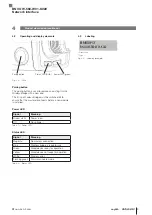
5.2.1 Power supply
Fig. 5-1:
3
1
4
2
5
Top view of M12 plug, A-coded
Pin
Signal
Description
1
L+
+24 V, module supply
2
–
n/a
3
L−
0 V (GND), module supply
4
–
n/a
5
–
n/a
Tab. 5-1: Power supply pin assignment
5
Installation and connection
5.2.2 IO-Link
Fig. 5-2:
3
5
4
2
1
Top view of M12 socket, A-coded
Pin
Signal
Description
1
L+
+24 V, IO-Link device supply
2
–
n/a
3
L−
0 V (GND), IO-Link device supply
4
C/Q
IO-Link communication
5
–
n/a
Tab. 5-2: Pin assignment of IO-Link interface
BNI IOW-560-W01-K022
Network interface
Summary of Contents for BNI IOW-560-W01-K022
Page 1: ...deutsch Betriebsanleitung english User s guide BNI IOW 560 W01 K022...
Page 2: ...www balluff com...
Page 3: ...BNI IOW 560 W01 K022 Betriebsanleitung deutsch...
Page 4: ...www balluff com...
Page 17: ...BNI IOW 560 W01 K022 User s Guide english...
Page 18: ...www balluff com...
Page 31: ......


