background image

www.balluff.com

9

english

6.1 

Startup

  DANGER

Uncontrolled system movement

When starting up, if the sensor is part of a closed loop 
system whose parameters have not yet been set, the 
system may perform uncontrolled movements. This 
could result in personal injury and equipment damage.


Persons must keep away from the system’s 
hazardous zones.


Startup must be performed only by trained technical 
personnel.


Observe the safety instructions of the equipment or 
system manufacturer.

  CAUTION

Red light

If you look into the light beam emitted by the transmitter, 
temporary blinding and irritation of the eyes is possible.


Do not look into the light beam!

1. 

Check connections for tightness and correct polarity. 

Replace damaged connections.

2. 

Turn on the system.

3. 

Check measured values and adjustable parameters 

and realign and adjust the sensor, if necessary.

Check for the correct values, especially after 

replacing the sensor or after repair by the 

manufacturer.

6.2 

Operation

  CAUTION

Red light

If you look into the light beam emitted by the transmitter, 
temporary blinding and irritation of the eyes is possible.


Do not look into the light beam!

No further protective measures are required for operation.

Configure sensors
1. 

Position the emitter and receiver to the desired 

distance.

2. 

Set the potentiometer to maximum sensitivity (greatest 

range).

3. 

Detect the on and off output switchpoint (yellow LED): 

move the emitter or receiver in multiple directions so 

that the switching state of the yellow LED on the 

receiver changes (on or off). Each switching state 

change indicates one switchpoint.

In order to detect very small objects, reduce the 

sensitivity and thus the range and adjust the 

positioning of the sensors.

4. 

Mount the sensor that was moved in the middle of the 

determined switchpoints. The system is operating 

optimally when the green LED of the receiver lights up 

and the yellow LED is off for the NO contact version 

and on for the NC contact version.

6.3 

Operating notes

–  Regularly check function of the sensor and all 

associated components.

–  Take the sensor out of service whenever there is a 

malfunction.

–  Check fasteners regularly and retighten if needed.

6.4 

Cleaning

Keep the lens as free from soiling as possible (dust etc.) 

and do not touch it (fingerprints).

Remove soiling


Wipe off the lens with a lint-free cloth and alcohol 

(ethanol, isopropanol).

6.5 

Maintenance

The product is maintenance-free.

Startup and operation

BOS R090K-_U-RX10-S49/S75/02

Optoelectronic sensors – Through-beam sensors

Summary of Contents for BOS R090K-U-RX10-S49 Series

Page 1: ...BOS R090K _U RX10 S49 BOS R090K _U RX10 S75 BOS R090K _U RX10 02 deutsch Betriebsanleitung english User s guide...

Page 2: ...www balluff com...

Page 3: ...BOS R090K _U RX10 S49 BOS R090K _U RX10 S75 BOS R090K _U RX10 02 Betriebsanleitung deutsch...

Page 4: ...www balluff com...

Page 5: ...i Empf nger 7 4 3 2 Empfindlichkeitseinstellung nur bei Empf nger 7 4 3 3 LED Anzeigen 7 5 Einbau und Anschluss 8 5 1 Einbau 8 5 2 Elektrischer Anschluss 8 6 Inbetriebnahme und Betrieb 9 6 1 Inbetrieb...

Page 6: ...rung Entsorgung 1 3 Verwendete Symbole und Konventionen Einzelne Handlungsanweisungen werden durch ein vorangestelltes Dreieck angezeigt Handlungsanweisung 1 Handlungsabfolgen werden nummeriert darges...

Page 7: ...f hrdeten Bereichen im Lebensmittelbereich 2 3 Allgemeine Sicherheitshinweise T tigkeiten wie Einbau Anschluss und Inbetriebnahme d rfen nur durch geschulte Fachkr fte erfolgen Eine geschulte Fachkraf...

Page 8: ...nter www balluff com auf der Produktseite 3 2 Transport Produkt in Originalverpackung bis zum Verwendungs ort transportieren 3 3 Lagerbedingungen Produkt in Originalverpackung lagern Umgebungsbedingun...

Page 9: ...LED leuchtet sobald der Sender aktiv ist Gr n2 Stabilit tsanzeige Die LED leuch tet sobald der Sensor betriebsbe reit ist und in einem sicheren Bereich arbeitet 1 nur bei Sender 2 nur bei Empf nger T...

Page 10: ...icht im Freien und nicht neben induktiven Ger ten oder W rmequellen montieren Den Sensor keinem direkten Sonnenlicht und keiner direkten Lichteinstrahlung aussetzen Die max Kabell nge betr gt 100 m be...

Page 11: ...Schutzma nahmen erforderlich Sensoren einstellen 1 Sender und Empf nger auf die gew nschte Entfernung positionieren 2 Das Potenziometer auf maximale Empfindlichkeit einstellen gr te Reichweite 3 Den...

Page 12: ...efekt sein nehmen Sie Kontakt mit unserem Service Center auf 7 2 Entsorgung Befolgen Sie die nationalen Vorschriften zur Entsor gung Weitere Informationen finden Sie unter www balluff com auf der Prod...

Page 13: ...g 30 V DC Laststrom 100 mA Spannungsabfall Laststrom 10 mA 1 2 V Laststrom 100 mA 2 V Schaltfrequenz 1000 Hz Reaktionszeit 0 5 ms Kurzschlussschutz ja Vertauschm glichkeit gesch tzt ja Verpolungssiche...

Page 14: ...mm Abstand m Lichtfleckdurchmesser 8 10 Zulassungen und Kennzeichnungen Mit dem CE Zeichen best tigen wir dass unsere Produkte den Anforderungen der aktuellen EU Richtlinie entsprechen N here Informat...

Page 15: ...BOS R090K _U RX10 S49 BOS R090K _U RX10 S75 BOS R090K _U RX10 02 User s Guide english...

Page 16: ...www balluff com...

Page 17: ...eceiver only 7 4 3 2 Sensitivity setting receiver only 7 4 3 3 LED indicators 7 5 Installation and connection 8 5 1 Installation 8 5 2 Electrical connection 8 6 Startup and operation 9 6 1 Startup 9 6...

Page 18: ...ing documents Data sheet Declaration of Conformity Disposal 1 3 Symbols and conventions Individual action instructions are indicated by a preceding triangle Instruction 1 Action sequences are numbered...

Page 19: ...In explosive atmospheres In food applications 2 3 General safety notes Activities such as installation connection and startup may only be carried out by qualified personnel Qualified personnel are per...

Page 20: ...essories can be found at www balluff com on the product page 3 2 Transport Transport product to location of use in original packaging 3 3 Storage conditions Store product in original packaging Observe...

Page 21: ...active Green2 Stability indicator The LED lights up as soon as the sensor is operational and is operating in a safe range 1 Transmitter only 2 Receiver only Tab 4 3 LED 4 1 Construction BOS R090K _U R...

Page 22: ...cals Do not install the sensor in the open or near inductive devices or sources of heat Do not expose the sensor to direct sunlight or other direct sources of light The max cable length is 100 m with...

Page 23: ...r protective measures are required for operation Configure sensors 1 Position the emitter and receiver to the desired distance 2 Set the potentiometer to maximum sensitivity greatest range 3 Detect th...

Page 24: ...the product is defective contact our Service Center 7 2 Disposal Observe the national regulations for disposal Additional information can be found at www balluff com on the product page 7 Repair and d...

Page 25: ...urrent 100 mA Voltage drop Load current 10 mA 1 2 V Load current 100 mA 2 V Switching frequency 1000 Hz Response time 0 5 ms Short circuit protection yes Protection against miswiring yes Polarity reve...

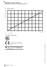
Page 26: ...t spot diameter mm Distance m Light spot diameter 8 10 Approvals and designations The CE Mark verifies that our products meet the requirements of the current EU Directive Additional information on dir...

Page 27: ......
Page 28: ...ngshan Rd 8F Building A Yunding International Commercial Plaza 200125 Pudong Shanghai Phone 86 400 820 0016 Fax 86 400 920 2622 service cn balluff com cn DACH Service Center Germany Balluff GmbH Schur...

Reviews: