BTL5-T1_ _-M_ _ _ _-A/B/Y/Z-SA366-S103
Micropulse Transducer – Rod Style
1
english
EU Directive 2004/108/EG (EMC Directive) and EMC law
Noise immunity: EN 61000-6-2
Emission: EN 61000-6-4
File No.
E227256
Intended use
The BTL5 Micropulse transducer is
intended to be installed in a machine
or system. Together with a controller
(PLC) or a master it comprises a
position measuring system and may
only be used for this purpose.
Installation
Ensure that no strong
electrical or magnetic
fields are present in the
immediate vicinity of the transducer.
The contact surface of the transducer
must be completely contacted by the
mounting surface. The O-ring supplied
must make a perfect pressure seal.
To achieve secure mounting, use the
proper nut for the mounting thread.
When tightening the nut, do not
exceed a tightening torque of 100 Nm.
For horizontal mounting of transducer
with stroke lengths greater than
500 mm, the pressure tube should
be supported or attached at its end.
When installing in a hydraulic cylinder,
do not allow the magnet ring to rub
against the pressure tube. The bore
diameter in the piston and cylinder rod
should be at least 13 mm. Permissible
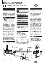
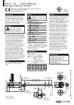
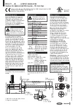
values for distance and center offset
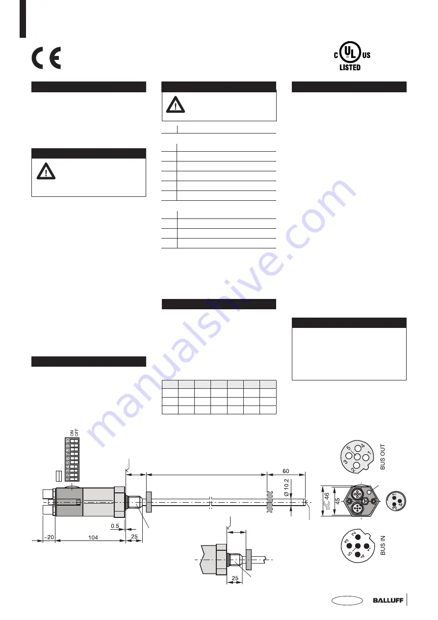
are indicated in the drawing.
SA366:
LED visible on front face via light
guide.
Startup
Observe all relevant safety regulations!
Check connections:
Components
can be damaged by improper
connections and overvoltage. Verify all
connections before applying power!
Turning on the system:
Note that
the system may execute uncontrolled
movements when the transducer is
part of a closed-loop system whose
parameters have not yet been set.
Therefore make sure that no hazards
could result from these situations.
Check functionality:
The functionality
of the transducer system and all its
associated components should be
regularly checked and recorded. In
particular, steps must be taken to
ensure that should the transducer
system become defective no hazards
to persons or property can result.
Fault conditions:
When there is
evidence that the transducer system
is not operating properly, it should
be taken out of service and guarded
against unauthorized use.
Wiring
System and control cabinet
must be at the same ground
potential.
No. 895 136 E • Edition 1303; Subject to modification.
➀
Not included.
Connector
➀
for Bus In / Bus Out:
straight: BKS-S103-00 / S105-00
right-angle: BKS-S104-00 / S106-00
Cable with connector
➀
for Power:
BKS-S 48-15-CP-_ _
Nominal length =
measuring range
Damping zone
Mounting surface
Magnet
➀
B: 30 -1 mm
Z: 2" -0.04 "
Thr
ead
M4 × 4/6 deep
Electrical connection
Pin BTL5-T1...S103
Data signals PROFIBUS-DP
Bus In / Bus Out
1
VP +5 V (output)
2
RxD / TxD-N (A)
3
Data GND
4
RxD / TxD-P (B)
5
Shield
Supply voltage (external)
Power
1
+24 V
3
0 V (GND)
4
Shield
Configuration
Station address:
Values from 0...127 allowed;
Value 0...125 = station address
Value 126 = address 126 or the
address set by
Set_Slave_Address
Value 127 = reset BTL to its default
condition
(female)
Power
(male)
View towards
connectors
(male)
Bus termination S1.9 and S1.10 = ON
User's Manual
A detailed user's manual and
configuration guide can be
obtained on the Internet at
www.balluff.com\downloads-btl5
or via e-mail to
PROFIBUS@balluff.de
Mounting
surface
Thread:
B: M18x1.5
Z: 3/4"-16UNF
A: 30 -1 mm
Y: 2" -0.04 "
Thread:
A: M18x1.5
Y: 3/4"-16UNF
➁
Unusable area.
➁
➁
S1
LED
S1.1 S1.2 S1.3 S1.4 S1.5 S1.6 S1.7
2
0
2
1
2
2
2
3
2
4
2
5
2
6
LSB
MSB
1
2
4
8
16
32
64
gr
een
re
d

