BTL6-A/G301-M_ _ _ _-A1-S115
Micropulse AT Transducer in round profile housing
3
english
0%
100%
100%
0%
Position
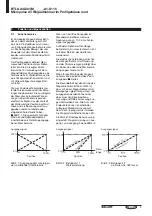
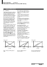
Fig. 2-1: Rising and falling output
signal
2.1
Function
The Micropulse transducer contains a
waveguide enclosed by an aluminum
housing. A magnet attached to the
moving member of the machine is
moved across the top of the housing
and its position constantly updated.
The magnet defines the measured
position on the waveguide. An inter-
nally generated current pulse inter-
acts with the magnetic field of the
magnet to generate a magnetostric-
tive torsional wave in the waveguide
which propagates at ultrasonic
speed.
The torsional wave arriving at the end
of the waveguide is absorbed in the
damping zone. The wave arriving at
the beginning of the waveguide
creates an electrical signal in the coil
surrounding the waveguide. The
propagation time of the wave is used
to derive the position. This is output
as a voltage value and may be rising
(increasing voltage) or falling
(decreasing voltage),
➥
➥
➥
➥
➥
Fig. 2-1. This
process takes place with measuring
high precision and repeatability within
the stroke range defined as nominal
stroke length.
When there is no magnet located in
the nominal stroke range, a signal of
approx. 10.5 V is output as an error
indication.
On both ends of the nominal stroke
length is an area which provides an
unreliable signal, but which may be
entered.
The electrical connection between
the transducer, the controller and the
power supply is via a cable with
connectors.
Dimensions for installing the Micro-
pulse transducer and for the magnets
are found on
➥
➥
➥
➥
➥
Page 4
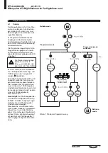
The unique feature of the
BTL6-A/G301 transducers is that
one transducers can be used to
sense two motions at the same time
and that you can select from
between single-position
measurement and differential
measurement. All zero and span
points can be separately
programmed within the permissible
stroke range using a teach-in
procedure. An LED is provided as a
programming aid.
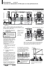
The factory setting is for single-
position sensing and programming of
Output 1 and Output 2, see Fig. 2-2.
2
Function and Characteristics
0%
100%
100 %
0 %
50%
Position
Output 1 (Pin 5)
Output 2 (Pin 3)
Fig. 2-2: Operating mode 1
Factory setting
Output signal
Output signal
Output signal
Output 2 (Pin 3)
Output 1 (Pin 5)
Position
Fig. 2-3: Operating mode 3
until Serial-No. 0531xxxxx
Nom.
stroke


