www.balluff.com
7
english
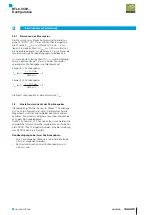
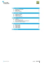
3.2.1 Calculating the measurement period
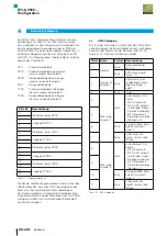
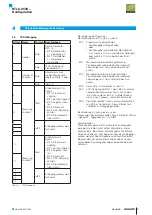
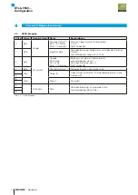
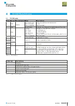
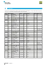
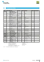
The BTL measurement period is set using the VARAN
client PLL SYNC_OUT_0 output. The cycle time t
period
must
be in the range of 0.25 ms to 4 ms. A value smaller than
0.25 ms for t
period
is limited by hardware, a value larger than
4 ms will restrict the maximum permissible positioning
speed.
t
min
, the smallest permissible value for t
period
, is calculated as
follows, depending on the nominal length L (in mm) and
the number of magnets used:
Formula for 1 magnet:
t
min
[ms] =
L + 100 mm
× 2
2800 m/s
Formula for 2 magnets:
t
min
[ms] =
L + 100 mm
× 3
2800 m/s
The measurement cycle frequency is the reciprocal
of the t
period
.
3.3
Setting the number of magnets
By default the sensor powers up in one-magnet mode (one
measurement channel is active). The user has the
possibility to activate the remaining measurement channels
also. The maximum available measurement channels can
be obtained via the 0x61E0 AI_Number_Of_Channels
service data object. The required number of active
measurement channels can be set in the RPDO offset 2
memory location. For an RPDO description see chapter 4.
Boundary conditions for two magnets
– Two magnets can only be selected if the nominal length
is ≥ 90 mm.
– The distance between two magnets must be ≥ 65 mm.
3
Startup (Fortsetzung)
BTL6-V55V…
Configuration
Summary of Contents for BTL6-V55 Series
Page 1: ...BTL6 V55 Konfigurationshandbuch deutsch...
Page 2: ...www balluff com...
Page 15: ...BTL6 V55 Configuration Manual english...
Page 16: ...www balluff com...

