


4
english
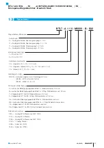
BTL7-A/C/E/G_ _ _-M_ _ _ _-A/B/Y/Z(8)-S32/S115/S135/S140/KA_ _/FA_ _
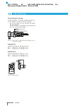
Micropulse Transducer - Rod Style
7
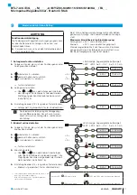
Calibration using teach-in
18
8
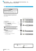
Calibration using adjustment
19
9
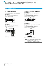
Calibration using online setting
21
10
Resetting all values (reset)
22
11
Technical data
23
11.1 Accuracy
23
11.2 Ambient conditions
23
11.3 Supply voltage (external)
23
11.4 Output
23
11.5 Input
23
11.6 Dimensions, weights
24
12
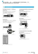
Accessories
25
12.1 Magnets
25
12.2 Mounting nut
25
12.3 Connectors and cables
26
12.3.1 BKS-S32/S33M-00, freely configurable
26
12.3.2 BKS-S232/S233-PU-_ _, preassembled
26
12.3.3 BKS-S115/S116-PU-_ _, preassembled
27
12.3.4 BKS-S135/S136M-00, freely configurable
27
12.3.5 BKS-S140-23-00, freely configurable
27
12.3.6 Plug-in system, 8-pin
28
13
Ordering code
29
14
Appendix
30
14.1 Converting units of length
30
14.2 Part label
30
Summary of Contents for BTL7 Series
Page 2: ...www balluff com...
Page 33: ...www balluff com...


