background image

6

english

2.1 

Intended use

The BTL7 Micropulse Transducer, together with a machine 

controller (e.g. PLC), comprises a position measuring 

system. It is intended to be installed into a machine or 

system. Flawless function in accordance with the 

specifications in the technical data is ensured only when 

using original BALLUFF accessories. Use of any other 

components will void the warranty.

Opening the transducer or non-approved use are not 

permitted and will result in the loss of warranty and liability 

claims against the manufacturer.

2.2 

General safety notes for the transducer 

system

Installation

 and 

startup

 may only be performed by 

trained specialists with basic electrical knowledge.

Qualified personnel 

are those who can recognize 

possible hazards and institute the appropriate safety 

measures due to their professional training, knowledge, 

and experience as well as their understanding of the 

relevant regulations pertaining to the work to be done.

The 

operator

 is responsible for ensuring that local safety 

regulations are observed.

In particular, the operator must take steps to ensure that a 

defect in the position measuring system will not result in 

hazards to persons or equipment.

If defects and unresolvable faults occur in the transducer, it 

should be taken out of service and secured against 

unauthorized use.

2.3 

Explanation of the warnings

Always observe the warnings in these instructions and the 

measures described to avoid hazards.

The warnings used here contain various signal words and 

are structured as follows:

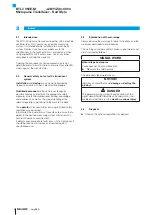
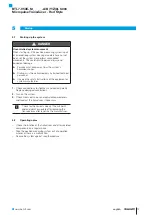
SIGNAL WORD

Hazard type and source

Consequences if not complied with


Measures to avoid hazards

The individual signal words mean:

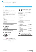
NOTICE!

Identifies a hazard that could 

damage

 or 

destroy the 

product.

  DANGER

The general warning symbol in conjunction with the 

signal word DANGER identifies a hazard which, if not 

avoided, will certainly result in 

death

 or 

serious injury

.

2.4 

Disposal


Observe the national regulations for disposal.

Safety

BTL7-V50E-M _ _ _ _ -A/B/Y/Z(8)-C003

Micropulse Transducer - Rod Style

Summary of Contents for BTL7-V50E-M P-C003 Series

Page 1: ...BTL7 V50E M_ _ _ _ A B Y Z 8 C003 Betriebsanleitung deutsch...

Page 2: ...www balluff com...

Page 3: ...inbauen 11 4 3 1 Einbauempfehlung f r Hydraulikzylinder 11 4 4 Elektrischer Anschluss 12 4 4 1 Steckverbinder BTL7 C003 12 4 5 Schirmung und Kabelverlegung 12 5 Inbetriebnahme 13 5 1 System in Betrieb...

Page 4: ...4 deutsch BTL7 V50E M_ _ _ _ A B Y Z 8 C003 Micropulse Wegaufnehmer Bauform Stab 8 Typenschl ssel 18 9 Anhang 19 9 1 Umrechnung L ngeneinheiten 19 9 2 Typenschild 19...

Page 5: ...7256 Eingetragene Marke und paten tierte Technologie Lizenziert durch die Beckhoff Automation GmbH Deutschland Mit dem CE Zeichen best tigen wir dass unsere Produkte den Anforderungen der EU Richtlini...

Page 6: ...en treffen kann Der Betreiber hat die Verantwortung dass die rtlich geltenden Sicherheitsvorschriften eingehalten werden Insbesondere muss der Betreiber Ma nahmen treffen dass bei einem Defekt des Weg...

Page 7: ...hen den Positionsgebern muss mindestens 65 mm betragen Bild 3 2 L Abstand zwischen den Positionsgebern Nennl nge Definiert den zur Verf gung stehenden Weg L ngenmessbereich Je nach Ausf hrung des Wega...

Page 8: ...le bertragen EtherCAT ist ein industrielles Bussystem das auf der physikalischen Schicht des Ethernets basiert siehe www ethercat org Der BTL7 ist in der Lage bis zu 16 Positionsgeber zu detektieren u...

Page 9: ...r Kommunikationsfehler ist aufgetreten Doppelter Blitz Zeit berschreitung Prozessdaten Watchdog Zeit berschreitung EtherCAT Watchdog Die Anwendung hat Zeit Limitierungen berschritten Einfacher Blitz L...

Page 10: ...b 4 1 Bohrungsdurchmesser bei Einbau in einen Hydraulik zylinder 4 2 Einbau vorbereiten Einbauvariante F r die Aufnahme des Wegaufnehmers und des Positionsgebers empfehlen wir nichtmagnetisier bares M...

Page 11: ...r Verschlei zu sch tzen Die Dimensionierung der Detaill sungen liegt in der Verantwortung des Zylinderherstellers Der Werkstoff des Gleitelements muss auf den Belastungs fall das eingesetzte Medium un...

Page 12: ...rbe Signal 1 YE gelb TX 2 WH wei RX 3 OG orange TX 4 BU blau RX Tab 4 3 Pinbelegung Steckverbinder C003 BUS IN OUT 4 5 Schirmung und Kabelverlegung Definierte Erdung Wegaufnehmer und Schaltschrank m s...

Page 13: ...Anlagen oder Systemher stellers beachten 1 Anschl sse auf festen Sitz und richtige Polung pr fen Besch digte Anschl sse tauschen 2 System einschalten 3 Messwerte und einstellbare Parameter pr fen und...

Page 14: ...nd IP 67 6 3 Spannungsversorgung extern Spannung stabilisiert4 10 30 V DC Restwelligkeit 0 5 VSS Stromaufnahme bei 24 V DC 120 mA bis 1524 mm 160 mA ab 1525 mm Einschaltspitzenstrom 500 mA 10 ms Verpo...

Page 15: ...P 1013 4S BTL P 1012 4R enthalten Distanzst ck 8 mm Material Polyoxymethylen POM Positionsgeber BTL5 P 4500 1 Elektromagnet Gewicht ca 90 g Geh use Kunststoff Betriebstemperatur 40 C bis 60 C BTL P 1...

Page 16: ...0434 020 Kabell nge 2 m BCC M314 0000 10 014 PS0434 050 Kabell nge 5 m 7 3 2 Versorgungskabel konfektioniert mit gewinkeltem M8 Stecker max 5 9 7 18 2 M8x1 27 Bild 7 4 Steckerverbinder Buchse gewinkel...

Page 17: ...x1 14 5 max 7 Bild 7 7 Steckerverbinder gerade gerade Typ Bestellcode BCC M414 E834 8G 668 PS54T2 020 BCC M414 E834 8G 668 PS54T2 050 BCC M414 E834 8G 668 PS54T2 100 BCC M414 E834 8G 668 PS54T2 150 BC...

Page 18: ...abdurchmesser 10 2 mm B metrisches Befestigungsgewinde M18x1 5 O Ring Stabdurchmesser 10 2 mm Y Zollgewinde 3 4 16UNF O Ring Stabdurchmesser 10 2 mm Z Zollgewinde 3 4 16UNF O Ring Stabdurchmesser 10 2...

Page 19: ...055 8 0 31496063 9 0 35433071 10 0 393700787 Tab 9 1 Umrechnungstabelle mm inch 1 inch 25 4 mm inch mm 1 25 4 2 50 8 3 76 2 4 101 6 5 127 6 152 4 7 177 8 8 203 2 9 228 6 10 254 Tab 9 2 Umrechnungstabe...

Page 20: ...nc 8125 Holton Drive Florence KY 41042 Phone 859 727 2200 Toll free 1 800 543 8390 Fax 859 727 4823 technicalsupport balluff com CN Service Center China Balluff Shanghai trading Co ltd Room 1006 Pujia...

Page 21: ...BTL7 V50E M_ _ _ _ A B Y Z 8 C003 User s Guide english...

Page 22: ...www balluff com...

Page 23: ...tallation 10 4 3 Installing the transducer 11 4 3 1 Installation recommendation for hydraulic cylinders 11 4 4 Electrical connection 12 4 4 1 Connector BTL7 C003 12 4 5 Shielding and cable routing 12...

Page 24: ...4 english BTL7 V50E M_ _ _ _ A B Y Z 8 C003 Micropulse Transducer Rod Style 8 Type code breakdown 18 9 Appendix 19 9 1 Converting units of length 19 9 2 Part label 19...

Page 25: ...technology Licensed by Beckhoff Automation GmbH Germany The CE Mark verifies that our products meet the requirements of EU Directive 2004 108 EC EMC Directive The transducer meets the requirements of...

Page 26: ...ns pertaining to the work to be done The operator is responsible for ensuring that local safety regulations are observed In particular the operator must take steps to ensure that a defect in the posit...

Page 27: ...be at least 65 mm Fig 3 2 L Distance between the magnets Nominal length Defines the available measuring range Rods with various nominal lengths from 25 mm to 7620 mm are available depending on the ve...

Page 28: ...the position This information is transferred via the EtherCAT interface EtherCAT is an industrial bus system based on the physical layer of the Ethernet see www ethercat org The BTL7 can detect and pr...

Page 29: ...ical application or communication error has occurred Double flash Timeout of process data watchdog timeout of EtherCAT watchdog The application has exceeded the time limits Single flash Local error Th...

Page 30: ...re diameter if installed in a hydraulic cylinder 4 2 Preparing for installation Installation note We recommend using non magnetizable material to mount the transducer and magnet Horizontal assembly If...

Page 31: ...a slide element to protect the rod end from wear Dimensioning of the detailed solutions is the responsibility of the cylinder manufacturer The slide element material must be suitable for the appropria...

Page 32: ...nal 1 YE yellow TX 2 WH white RX 3 OG orange TX 4 BU blue RX Tab 4 3 Pin assignment of C003 connector BUS IN OUT 4 5 Shielding and cable routing Defined ground The transducer and the control cabinet m...

Page 33: ...quipment or system manufacturer 1 Check connections for tightness and correct polarity Replace damaged connections 2 Turn on the system 3 Check measured values and adjustable parameters and readjust t...

Page 34: ...Voltage stabilized4 10 to 30 V DC Ripple 0 5 VSS Current draw at 24 V DC 120 mA up to 1524 mm 160 mA from 1525 mm Inrush current 500 mA 10 ms Reverse polarity protection Up to 36 V Overvoltage protect...

Page 35: ...r the BTL P 1013 4R BTL P 1013 4S BTL P 1012 4R Spacer 8 mm material polyoxymethylene POM BTL5 P 4500 1 magnet solenoid Weight Approx 90 g Housing Plastic Operating temperature 40 C to 60 C BTL P 1028...

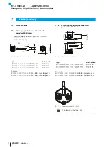
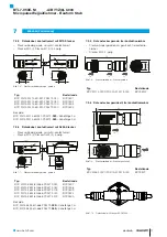
Page 36: ...cable length of 2 m BCC M314 0000 10 014 PS0434 050 cable length of 5 m 7 3 2 Power cable preassembled with angled M8 plug max 5 9 7 18 2 M8x1 27 Fig 7 4 Connector angled socket Type Ordering code BCC...

Page 37: ...14 M12x1 14 5 max 7 Fig 7 7 Straight straight connector Type Ordering code BCC M414 E834 8G 668 PS54T2 020 BCC M414 E834 8G 668 PS54T2 050 BCC M414 E834 8G 668 PS54T2 100 BCC M414 E834 8G 668 PS54T2...

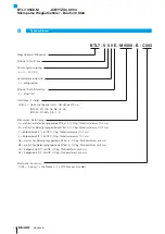
Page 38: ...c mounting thread M18x1 5 O ring rod diameter 10 2 mm B Metric mounting thread M18x1 5 O ring rod diameter 10 2 mm Y 3 4 16UNF thread O ring rod diameter 10 2 mm Z 3 4 16UNF thread O ring rod diameter...

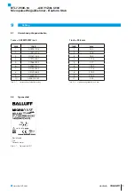
Page 39: ...5 8 0 31496063 9 0 35433071 10 0 393700787 Tab 9 1 Conversion table mm to inches 1 inch 25 4 mm inch mm 1 25 4 2 50 8 3 76 2 4 101 6 5 127 6 152 4 7 177 8 8 203 2 9 228 6 10 254 Tab 9 2 Conversion tab...

Page 40: ...Inc 8125 Holton Drive Florence KY 41042 Phone 859 727 2200 Toll free 1 800 543 8390 Fax 859 727 4823 technicalsupport balluff com CN Service Center China Balluff Shanghai trading Co ltd Room 1006 Puj...

Page 41: ...BTL7 V50E M_ _ _ _ A B Y Z 8 C003 Manual de instrucciones espa ol...

Page 42: ...www balluff com...

Page 43: ...ontaje del transductor de desplazamiento 11 4 3 1 Recomendaci n de montaje para cilindros hidr ulicos 11 4 4 Conexi n el ctrica 12 4 4 1 Conector BTL7 C003 12 4 5 Blindaje y tendido de cables 12 5 Pue...

Page 44: ...TL7 V50E M_ _ _ _ A B Y Z 8 C003 Transductor de desplazamiento Micropulse forma constructiva de varilla 8 C digo de modelo 18 9 Anexo 19 9 1 Conversi n de unidades de longitud 19 9 2 Placa de caracter...

Page 45: ...on GmbH Alemania Con el marcado CE confirmamos que nuestros productos cumplen con los requerimientos de la directiva de la UE 2004 108 CE directiva CEM El transductor de desplazamiento cumple con los...

Page 46: ...das El explotador es responsable de respetar las normas de seguridad locales vigentes En particular el explotador debe adoptar medidas destinadas a evitar peligros para las personas y da os materiales...

Page 47: ...65 mm como m nimo Fig 3 2 L Distancia entre los sensores de posici n Longitud nominal define la zona medible de desplazamiento longitud disponible Seg n la versi n del transductor de desplazamiento s...

Page 48: ...trav s de la interfaz EtherCAT EtherCAT es un sistema de bus industrial basado en la capa f sica de Ethernet v ase www ethercat org El BTL7 es capaz de detectar y procesar hasta 16 sensores de posici...

Page 49: ...aplicaci n Se ha producido un error grave de aplicaci n o comunicaci n Destello doble Tiempo excedido watchdog de datos de proceso tiempo excedido watchdog de EtherCAT La aplicaci n ha excedido l mite...

Page 50: ...idr ulico 4 2 Preparaci n del montaje Variante de montaje para alojar el transductor de desplazamiento y el sensor de posici n recomendamos un material no imantable Montaje horizontal en el montaje ho...

Page 51: ...las soluciones detalladas es responsabilidad del fabricante del cilindro El material del elemento de deslizamiento se debe adaptar a la carga correspondiente el medio empleado y las temperaturas resu...

Page 52: ...4 3 Asignaci n de pines del conector C003 BUS IN OUT 4 5 Blindaje y tendido de cables Puesta a tierra definida El transductor de desplazamiento y el armario el ctrico deben estar a id ntico potencial...

Page 53: ...n asentadas firmemente y tengan la polaridad correcta Sustituya las conexiones da adas 2 Conecte el sistema 3 Compruebe los valores de medici n y los par metros ajustables y en caso necesario reajust...

Page 54: ...0 5 VSS Consumo de corriente con 24 V DC 120 mA hasta 1524 mm 160 mA de 1525 mm Corriente de pico 500 mA 10 ms Protecci n contra polaridad inversa Hasta 36 V Protecci n contra sobretensiones Hasta 36...

Page 55: ...BTL P 1012 4R incluye Elemento distanciador 8 mm material polioximetileno POM Sensor de posici n BTL5 P 4500 1 electroim n Peso Aprox 90 g Carcasa Material sint tico Temperatura de servicio De 40 C a...

Page 56: ...000 10 014 PS0434 050 longitud de cable 5 m 7 3 2 Cable de alimentaci n confeccionado con conector M8 acodado max 5 9 7 18 2 M8x1 27 Fig 7 4 Conector con hembra acodado Modelo C digo de pedido BCC M32...

Page 57: ...7 Fig 7 7 Conector recto recto Modelo C digo de pedido BCC M414 E834 8G 668 PS54T2 020 BCC M414 E834 8G 668 PS54T2 050 BCC M414 E834 8G 668 PS54T2 100 BCC M414 E834 8G 668 PS54T2 150 BCC M414 E834 8G...

Page 58: ...sca de fijaci n m trica M18x1 5 junta t rica di metro de varilla 10 2 mm Y rosca inglesa 3 4 16UNF junta t rica di metro de varilla 10 2 mm Z rosca inglesa 3 4 16UNF junta t rica di metro de varilla 1...

Page 59: ...3700787 Tab 9 1 Tabla de conversi n mm pulgadas 1 pulgada 25 4 mm pulga das mm 1 25 4 2 50 8 3 76 2 4 101 6 5 127 6 152 4 7 177 8 8 203 2 9 228 6 10 254 Tab 9 2 Tabla de conversi n pulgadas mm 9 Anexo...

Page 60: ...Balluff Inc 8125 Holton Drive Florence KY 41042 Phone 859 727 2200 Toll free 1 800 543 8390 Fax 859 727 4823 technicalsupport balluff com CN Service Center China Balluff Shanghai trading Co ltd Room 1...

Page 61: ...BTL7 V50E M_ _ _ _ A B Y Z 8 C003 Notice d utilisation fran ais...

Page 62: ...www balluff com...

Page 63: ...pteur de d placement 11 4 3 1 Recommandation de montage pour v rin hydraulique 11 4 4 Raccordement lectrique 12 4 4 1 Connecteur BTL7 C003 12 4 5 Blindage et pose des c bles 12 5 Mise en service 13 5...

Page 64: ...4 fran ais BTL7 V50E M_ _ _ _ A B Y Z 8 C003 Capteur de d placement Micropulse Forme tige 8 Code de type 18 9 Annexe 19 9 1 Conversion unit s de longueur 19 9 2 Plaque signal tique 19...

Page 65: ...certifi e par Beckhoff Automation GmbH Allemagne Avec le symbole CE nous certifions que nos produits r pondent aux exigences de la directive europ enne 2004 108 UE directive CEM Le capteur de d place...

Page 66: ...res de s curit ad quates Il est de la responsabilit de l exploitant de veiller ce que les dispositions locales concernant la s curit soient respect es L exploitant doit en particulier prendre les mesu...

Page 67: ...teurs de position doit tre de 65 mm Fig 3 2 L Distance entre les capteurs de position Longueur nominale d finit la course plage de mesure disponible Selon la version le capteur de d placement est disp...

Page 68: ...par l interface EtherCAT EtherCAT est un syst me bus industriel bas sur la couche physique de l Ethernet voir www ethercat org Le BTL7 est capable de d tecter et g rer jusqu 16 capteurs de position Le...

Page 69: ...u de communication est survenue Deux flashs Temporisation d pass e chien de garde donn es de processus temporisation d pass e chien de garde EtherCAT L application a d pass les limites de temps Un fla...

Page 70: ...e montage dans un v rin hydraulique 4 2 Pr paration du montage Variante de montage pour la fixation des capteurs de d placement et de position nous recommandons l utilisation de mat riaux non magn tis...

Page 71: ...ent coulissant afin d viter toute usure pr matur e de l extr mit de la tige Le dimensionnement des solutions d taill es incombe au fabricant du v rin Le mat riau de cet l ment coulissant doit tre adap...

Page 72: ...ange TX 4 BU bleu RX Tab 4 3 Affectation des broches du connecteur C003 BUS IN OUT 4 5 Blindage et pose des c bles Mise la terre d finie Le capteur de d placement et l armoire lectrique doivent tre re...

Page 73: ...du fabricant doivent tre respect es 1 V rifier la fixation et la polarit des raccordements Remplacer les raccordements endommag s 2 Mettre le syst me en marche 3 V rifier les valeurs mesur es et les p...

Page 74: ...ndulation r siduelle 0 5 VSS Consommation de courant 24 V CC 120 mA jusqu 1524 mm 160 mA partir de 1525 mm Courant de cr te au d marrage 500 mA 10 ms Protection contre l inversion de polarit Jusqu 36...

Page 75: ...L P 1013 4R BTL P 1013 4S BTL P 1012 4R Bague d cartement 8 mm polyoxym thyl ne POM Capteur de position BTL5 P 4500 1 lectro aimant Poids Env 90 g Bo tier Plastique Temp rature de service 40 C 60 C BT...

Page 76: ...C M314 0000 10 014 PS0434 050 longueur de c ble 5 m 7 3 2 C ble d alimentation confectionn avec connecteur M8 coud max 5 9 7 18 2 M8x1 27 Fig 7 4 Connecteur douille coud e Type Symbolisation commercia...

Page 77: ...x1 14 5 max 7 Fig 7 7 Connecteur droit droit Type Symbolisation commerciale BCC M414 E834 8G 668 PS54T2 020 BCC M414 E834 8G 668 PS54T2 050 BCC M414 E834 8G 668 PS54T2 100 BCC M414 E834 8G 668 PS54T2...

Page 78: ...letage de fixation m trique M18x1 5 joint torique diam tre de tige 10 2 mm Y filetage au pouce 3 4 16UNF joint torique diam tre de tige 10 2 mm Z filetage au pouce 3 4 16UNF joint torique diam tre de...

Page 79: ...6063 9 0 35433071 10 0 393700787 Tab 9 1 Conversion mm pouce 1 pouce 25 4 mm pouce mm 1 25 4 2 50 8 3 76 2 4 101 6 5 127 6 152 4 7 177 8 8 203 2 9 228 6 10 254 Tab 9 2 Conversion pouce mm 9 Annexe 9 2...

Page 80: ...ff Inc 8125 Holton Drive Florence KY 41042 Phone 859 727 2200 Toll free 1 800 543 8390 Fax 859 727 4823 technicalsupport balluff com CN Service Center China Balluff Shanghai trading Co ltd Room 1006 P...

Page 81: ...BTL7 V50E M_ _ _ _ A B Y Z 8 C003 Manuale d uso italiano...

Page 82: ...www balluff com...

Page 83: ...di posizione 11 4 3 1 Suggerimento di montaggio per cilindro idraulico 11 4 4 Collegamento elettrico 12 4 4 1 Connettori BTL7 C003 12 4 5 Schermatura e posa dei cavi 12 5 Messa in funzione 13 5 1 Mes...

Page 84: ...V50E M_ _ _ _ A B Y Z 8 C003 Trasduttore di posizione Micropulse versione a barra 8 Legenda codici di identificazione 18 9 Appendice 19 9 1 Conversione delle unit di lunghezza 19 9 2 Targhetta di ide...

Page 85: ...evettata Concesso in licenza da Beckhoff Automation GmbH Germania Il marchio CE la conferma che i nostri prodotti sono conformi ai requisiti della Direttiva UE 2004 108 CE direttiva CEM Il trasduttore...

Page 86: ...di adottare misure di sicurezza adeguate Il gestore ha la responsabilit di far rispettare le norme di sicurezza vigenti localmente In particolare il gestore deve adottare provvedimenti tali da poter...

Page 87: ...ri di posizione deve corrispondere ad almeno 65 mm Fig 3 2 L Distanza tra i datori di posizione Lunghezza nominale definisce il campo di misura della corsa lunghezza disponibile A seconda della versio...

Page 88: ...ormazione viene trasmessa tramite l interfaccia EtherCAT EtherCAT un sistema bus industriale che si basa sullo strato fisico di Ethernet vedere www ethercat org Il BTL7 in grado di rilevare ed elabora...

Page 89: ...errore di applicazione o di comunicazione critico Doppio lampeggio Superamento tempo watchdog dati di processo superamento tempo watchdog EtherCAT L applicazione ha superato i limiti di tempo Lampeggi...

Page 90: ...parazione del montaggio Variante di montaggio per l installazione del trasduttore e del datore di posizione si consiglia l impiego di materiale non magnetizzabile Montaggio orizzontale per il montaggi...

Page 91: ...ggere l estremit della barra da usura Il dimensionamento delle soluzioni dettagliate responsabilit del produttore di cilindri Il materiale dell elemento scorrevole deve essere adattato al caso di cari...

Page 92: ...one TX 4 BU blu RX Tab 4 3 Piedinatura connettore C003 BUS IN OUT 4 5 Schermatura e posa dei cavi Messa a terra definita Il trasduttore di posizione e l armadio elettrico devono trovarsi sullo stesso...

Page 93: ...are che i collegamenti siano fissati saldamente e che la loro polarit sia corretta Sostituire i collegamenti danneggiati 2 Attivare il sistema 3 Controllare i valori misurati e i parametri regolabili...

Page 94: ...ne residua 0 5 VSS Corrente assorbita con 24 V DC 120 mA fino a 1524 mm 160 mA da 1525 mm Corrente massima di avviamento 500 mA 10 ms Protezione inversione di polarit fino a 36 V Protezione contro la...

Page 95: ...13 4R BTL P 1013 4S BTL P 1012 4R Distanziale 8 mm materiale poliossimetilene POM Datore di posizione BTL5 P 4500 1 elettromagnete Peso ca 90 g Supporto materiale plastico Temperatura di esercizio da...

Page 96: ...CC M314 0000 10 014 PS0434 050 lunghezza cavo 5 m 7 3 2 Cavo di alimentazione confezionato con connettore M8 ad angolo max 5 9 7 18 2 M8x1 27 Fig 7 4 Connettore a spina presa ad angolo Tipo Codice d o...

Page 97: ...7 7 Connettore a spina diritto diritto Tipo Codice d ordine BCC M414 E834 8G 668 PS54T2 020 BCC M414 E834 8G 668 PS54T2 050 BCC M414 E834 8G 668 PS54T2 100 BCC M414 E834 8G 668 PS54T2 150 BCC M414 E8...

Page 98: ...metro barra 10 2 mm B filettatura di fissaggio metrica M18x1 5 O ring diametro barra 10 2 mm Y filettatura in pollici 3 4 16UNF O ring diametro barra 10 2 mm Z filettatura in pollici 3 4 16UNF O ring...

Page 99: ...0 393700787 Tab 9 1 Tabella di conversione mm pollici 1 pollice 25 4 mm pollici mm 1 25 4 2 50 8 3 76 2 4 101 6 5 127 6 152 4 7 177 8 8 203 2 9 228 6 10 254 Tab 9 2 Tabella di conversione pollici mm...

Page 100: ...f Inc 8125 Holton Drive Florence KY 41042 Phone 859 727 2200 Toll free 1 800 543 8390 Fax 859 727 4823 technicalsupport balluff com CN Service Center China Balluff Shanghai trading Co ltd Room 1006 Pu...

Reviews: